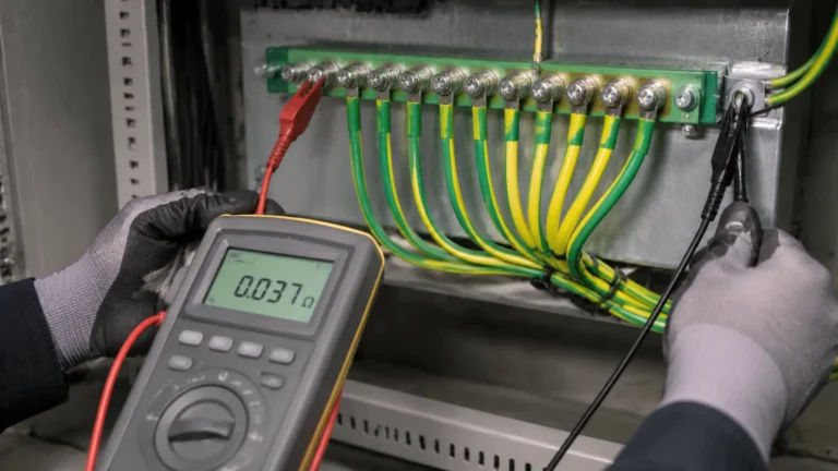
Brass vs Copper Neutral Bar: Which Conductor Belongs in Your Panel?
Published: Author: Rachel
The brass vs copper neutral bar question is often settled on conductivity alone, which is the part of the comparison that matters least.
This guide sets out the brass vs copper neutral bar comparison in practical terms: conductivity, contact resistance, corrosion behaviour and where each material belongs.
Ask which neutral bar material is better and the usual answer comes back in one number: copper conducts roughly three and a half times better than brass, therefore copper wins. That number is correct. The conclusion drawn from it is mostly wrong, and panels have been built the wrong way round for decades because of it.
A neutral bar is not a long-distance conductor. It is a short, fat piece of metal whose job is to be a mechanical clamping structure. Once you put actual dimensions on it and run the arithmetic, the resistivity difference between brass and copper accounts for about one watt of heat at full load — while a single badly torqued screw at one position accounts for twenty. This guide separates the material property that matters from the one that merely sounds impressive, and gives you a defensible way to choose. For the geometry and format choices that go with the material decision, see Types of Neutral Bar; for the sizing arithmetic, see Neutral Bar Size Chart.
The Quick Answer
For the majority of panel applications, a brass neutral bar is the correct default. It holds screw torque over time better than pure copper, it machines into cleaner threads, it resists the slow deformation that loosens terminations, and it costs less. Pure copper earns its place where the bar is long, the current is genuinely continuous at the top of the rating, or where the design relies on the bar itself to carry heat away from a dense cluster of terminations. The conductivity gap is real but it is not the deciding factor at the lengths a neutral bar actually works over.
Conductivity: A 3.6x Gap That Barely Matters Here
The standard figures, measured against the International Annealed Copper Standard, are these:
Material
Conductivity
Resistivity
Thermal conductivity
Pure copper (C110 / T2)
100% IACS
1.72 x 10^-8 ohm m
about 400 W/m K
Brass (CuZn37 / H62)
about 28% IACS
6.0 x 10^-8 ohm m
about 120 W/m K
Brass (CuZn30)
about 30% IACS
5.99 x 10^-8 ohm m
about 120 W/m K
Now put those numbers into a real component. Take a common panel-mounted format — a 3 x 25 mm cross-section bar, 75 mm² of metal, 200 mm long, carrying 100 A. The resistance of the bar as a conductor, end to end:
Material
Bar resistance
I²R loss at 100 A
Voltage drop end to end
Pure copper
0.046 mΩ
0.46 W
4.6 mV
Brass
0.16 mΩ
1.6 W
16 mV
Difference
0.11 mΩ
1.1 W
11 mV
That is the entire penalty for choosing brass: 1.1 watts, spread along 200 mm of metal that is 25 mm wide and bolted to a steel backplane. It is not nothing — but as a proportion of the heat this assembly produces, it is noise. The millivolt drop is roughly a thousandth of the supply voltage and disappears into the tolerances of everything else in the circuit.
What Actually Heats a Neutral Bar: Contact Resistance
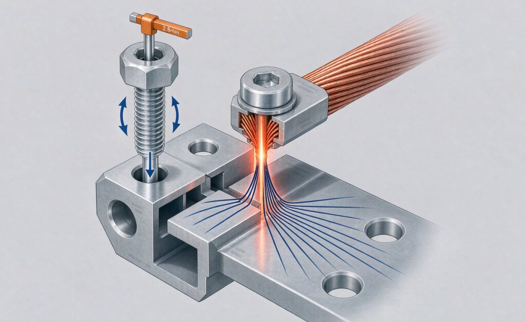
The heat in a termination does not come from the bulk metal. It comes from the contact interface, where current is squeezed through a small number of asperity points between the screw face, the conductor and the bar. That interface has a resistance measured in fractions of a milliohm, and it is entirely a function of how well the joint was made.
Joint condition
Typical contact resistance
Heat at 100 A
Comment
Clean, correctly torqued
0.1 to 0.3 mΩ
1 to 3 W
The target; stable for decades
Acceptable but not ideal
0.3 to 0.8 mΩ
3 to 8 W
Common in the field
Under-torqued or lightly oxidised
1 to 3 mΩ
10 to 30 W
Warm to the touch
Loose, oxidised, or doubled conductor
5 mΩ and above
50 W and above
Discolouration, then failure
Read that table against the previous one. Choosing brass over copper costs 1.1 W. Choosing to under-torque a single screw costs ten to thirty times as much, at one position, and it gets worse with every thermal cycle. The material choice is a one-off, permanent, 1 W decision. The workmanship choice is a recurring, per-termination, 10 W decision.
This is also why the neutral bar versus ground bar distinction matters more than the metallurgy: a bar carrying continuous return current through many terminations is a thermal management problem, and the termination quality dominates it.
Mechanical Behaviour Under the Screw
Here is where brass genuinely wins, and where the conductivity argument quietly reverses. A neutral bar is a threaded clamp. Its electrical performance over twenty years depends on whether that clamp still exerts force after twenty years of thermal cycling.
Property
Pure copper (annealed)
Brass (H62, half-hard)
Why it matters in a bar
Vickers hardness
about 40 HV
about 120 HV
Resists screw embedment and galling
Tensile strength
200 to 250 MPa
450 MPa and above
Thread stripping resistance
Stress relaxation at elevated temperature
Significant above roughly 80 °C
Markedly better
Clamp force retention over time
Machinability
Gummy, poor chip break
Excellent
Cleaner tapped threads, better screw feel
The third row is the one that gets overlooked. Under sustained compressive load, and increasingly as a joint runs warm, annealed copper creeps — it cold-flows away from the clamping point. The screw does not visibly turn; the clamping force simply decays, contact resistance climbs, the joint runs hotter, and the creep accelerates. This is a slow positive feedback loop, and it is one reason copper terminations are more often found loosened on inspection than brass ones of the same age. Brass relaxes far less under the same conditions.
Thread quality follows from the same properties. Brass taps cleanly and holds a thread that survives repeated removal and re-tightening. Soft copper threads are more prone to damage when an installer over-torques or crosses a screw — and a damaged thread cannot be re-torqued to specification at all, which converts a minor assembly error into a permanent hot spot.
Heat Spreading: The Round Copper Does Win
There is one thermal argument for copper that survives scrutiny, and it is not bulk resistance. Copper’s thermal conductivity is roughly 3.4 times that of brass, so a copper bar moves heat away from a hot termination and distributes it along the bar and into the mounting structure more effectively. A local hot spot on a copper bar is less local than the same hot spot on a brass bar.
This matters in a specific configuration: a long bar, densely populated, carrying continuous current near its rating, in an enclosure with little airflow. In that case the bar is acting as a heat spreader as much as a conductor, and copper does the spreading better. It matters very little on a short bar with a handful of lightly loaded terminations, where every joint is effectively cooled by its own surroundings.
Corrosion: Two Different Failure Modes
Both metals corrode, by different mechanisms, and both are routinely protected by plating.
Material
Corrosion mechanism
What it looks like
Standard protection
Pure copper
Surface oxidation to CuO / Cu2O
Dark brown to black tarnish; high-resistance film at the contact face
Tin or nickel plating
Brass
Dezincification in ammoniacal or persistently damp environments
Reddish, porous, weakened metal
Nickel plating; low-zinc alloy selection
Copper oxide is a poor conductor, so an unplated copper bar that has sat in a humid enclosure develops a resistive film exactly where it can do the most damage. Brass oxidises more slowly at the contact face but will dezincify under sustained exposure to ammonia, certain cleaning agents, or marine atmospheres — leaving a porous copper-rich sponge with little mechanical strength.
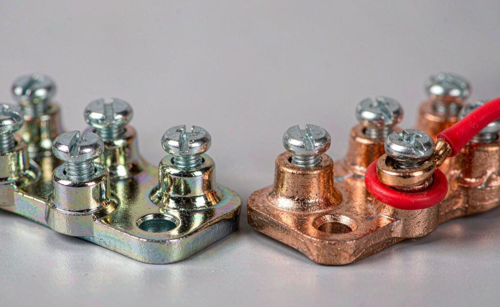
In practice both are handled the same way: plate the bar. Nickel plating is the common choice for brass bars because it also raises surface hardness and gives a consistent, low-friction screw interface. Tin plating appears where compatibility with aluminium conductors or a softer contact surface is wanted. An unplated bar of either material is the version to be suspicious of.
Cost, Machining and Supply
Brass is the cheaper input per kilogram, cuts faster, and produces less tool wear — all of which show up in the unit price of a drilled-and-tapped bar. It is also the reason brass dominates the low and middle range of the market. Copper commands a premium both for the raw material and for the slower, more wasteful machining. Where the specification genuinely calls for copper, the premium is usually worth paying; where it does not, it buys a conductivity advantage worth roughly one watt.
There is a supply-side argument too. Brass bar stock in the common neutral-bar formats — 1.5 x 15, 2 x 20, 3 x 25 mm — is produced in far greater volume, which shortens lead times on custom way-counts and odd hole patterns.
Where Each Material Belongs
Application
Recommended material
Reason
Standard residential or light commercial load centre
Brass, nickel-plated
Torque retention and thread durability dominate; current is well within rating
Subpanel with an isolated floating bar
Brass, nickel-plated
Same reasoning; no bonding requirement to satisfy
Dense distribution board, continuous load near rating
Copper
Heat spreading along the bar is doing real work
Long bar runs, many ways, high ambient temperature
Copper
Bulk resistance and spreading both start to matter at length
Humid, coastal or ammoniacal environment
Either, but plated
Plating matters more than substrate; inspect periodically
Cost-sensitive OEM build, moderate duty
Brass
Lowest cost per termination with no practical penalty
Equipment ground bar bonded to the enclosure
Either
Carries fault current only; conductivity is not the constraint
What This Means for the Bar You Order
The practical reading is that you can specify brass with confidence for the overwhelming majority of panels, and spend the saved money on the things that actually determine termination reliability: correct torque, correct conductor preparation, and enough ways that no terminal is ever asked to accept two conductors. The neutral bar article covers the wiring rules that go with the hardware, and ground bar installation covers the torque and preparation discipline in step form.
The bars below cover the plain bar, bracket-mounted, DIN rail and fully covered options discussed above. Copper and brass versions are available in the same footprints, so the mounting decision and the material decision stay separate.
Only when the bar is long, densely loaded, and running close to its rating in a warm enclosure — that is when heat spreading along the bar does real work. In a standard load centre with modest continuous load, the brass bar will perform identically over its service life and costs less.
Does the lower conductivity of brass make the bar run hot?
Not measurably. On a 200 mm, 75 mm² bar at 100 A the brass bar dissipates about 1.1 W more than an equivalent copper bar. A single under-torqued screw dissipates ten to thirty times that. Bulk resistivity is not what makes terminations hot.
Can I mix brass and copper in the same panel?
Yes, and it is common — a brass neutral bar alongside a copper ground bar, for example. Both are copper alloys with compatible galvanic behaviour in a dry indoor enclosure. What matters is that each conductor is terminated on a bar rated for that conductor’s material, and that dissimilar conductor metals are not placed under the same screw.
Why are so many brass bars nickel-plated?
Nickel raises surface hardness and wear resistance at the screw interface, slows dezincification, and gives a stable low-friction contact surface. It is a mechanical and corrosion treatment rather than an electrical one — nickel itself conducts less well than either substrate, but the plating is thin enough that it does not change the bulk behaviour.
Does material choice affect the ampacity rating of the bar?
It affects the rating the manufacturer can claim, because a copper bar of a given section will pass a lower temperature rise than the same section in brass. It does not change how you should apply the bar: use the manufacturer’s stated rating for the specific model, not a material-based rule of thumb. The sizing procedure works from the rated value, whichever material the bar is made of.
The Bottom Line
Brass versus copper is a conductivity argument that has been applied to a component whose performance is not conductivity-limited. Over the 100 to 300 mm that a neutral bar works across, the material difference is worth about a watt; over the same distance, one badly made termination is worth twenty to fifty. Brass holds clamp force better, survives re-tightening better, threads better and costs less, which makes it the right default for most panels. Copper earns its premium in the narrow band where the bar is long, continuously loaded near rating, and being asked to spread heat — and in that band, it is worth specifying deliberately rather than by reflex.
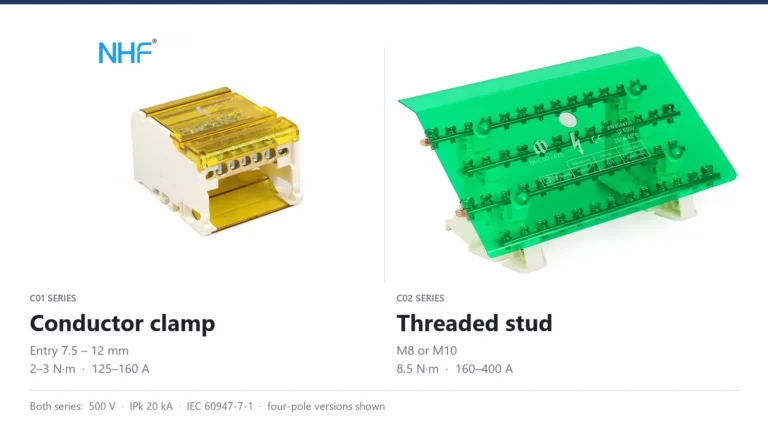
Both ranges are rated 500 V and IPk 20 kA, so the data sheet cannot choose for you. The difference sits at the input terminal: a conductor clamp with a published conductor range, or a stud that holds a cable lug.
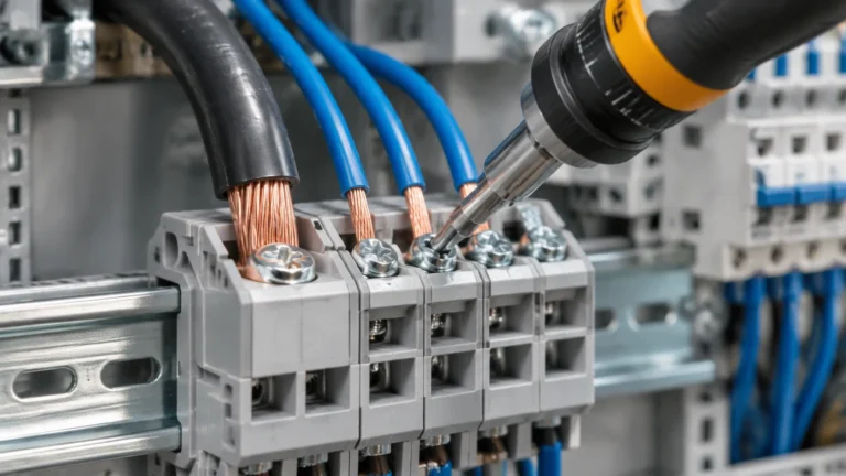
Four rules decide whether a terminal block joint runs cool or overheats: the strip length the block specifies, the separate input and output torque values, one rated conductor per clamp, and the conductor range for the ferruled size.
How to test earth continuity on a grounding bar: the dead test method, instrument and test current selection, acceptance values in ohms, and the parallel-path mistake that invalidates results.