Terminal Block Wiring: Strip Length, Torque and Clamp Rules
Published: Author: Rachel
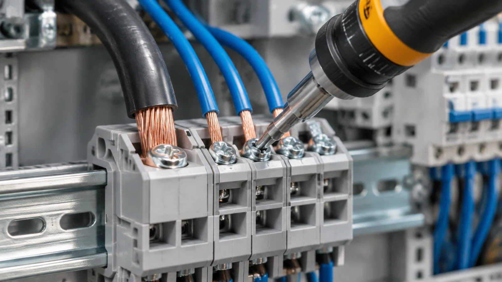
Terminal block wiring fails for one reason far more often than any other: the conductor was not prepared or clamped the way that specific block requires. This guide sets out the four rules that decide whether a joint stays cool for twenty years or heats up in six months, using the actual input and output ratings published for our distribution blocks.
Quick answer: strip to the length the block specifies rather than to a habit, tighten the input and output terminals to their own separate torque values, put no more than one rated conductor in a clamp unless the data sheet explicitly permits a combination, and verify the result with a voltage drop measurement rather than by tugging the wire.
Why a connection that looks tight still overheats
Every connection has resistance, and that resistance converts current into heat inside a space a few millimetres across. The relationship is P = I² × R. An extra 0.01 Ω in a joint carrying 20 A dissipates 4 W in that one spot, with a 0.2 V drop across it. Double the current and the loss quadruples to 16 W.
That is why a terminal can be hot enough to discolour its housing while the circuit breaker upstream never trips. The breaker responds to the current in the circuit, not to the temperature of a bad joint. Fitting a larger breaker makes the problem worse rather than better.
The failure then follows a predictable sequence. Insufficient clamp pressure gives a high-resistance joint. The joint runs hot. Thermal cycling plus panel vibration loosens the screw further. Contact pressure falls again and resistance rises again. What began as a slightly under-torqued screw ends as a burned terminal. The joint was already wrong on the day it was made; it simply took a year to show.
There are four things that decide whether that sequence starts, and each one has a published value attached to it.
Rule 1: strip length comes from the block, not from habit
Strip too little and the conductor does not reach the clamping zone, so the screw bites on insulation and the electrical contact is whatever the insulation will pass. Strip too much and bare copper stands proud of the clamp, reducing the clearance and creepage distance to the next potential and leaving a length of conductor with no mechanical support.
Neither error is visible from the front of a closed panel, and both survive a tug test, which is why strip length has to be specified rather than judged.
The correct value is product-specific. It is published in the data sheet and it varies with the clamping system, not with the conductor. As published examples from other manufacturers: a Phoenix Contact UT 2,5 specifies 9 mm, and WAGO rail-mount blocks in the 2002 and 2222 series specify 10 to 12 mm. Those are their values for their blocks. Our blocks are dimensioned for the metric conductor range in their own data sheets, and the figure to work to is the one on the sheet for the part in your hand.
Two consequences follow that catch people out.
A strip length quoted in inches is a warning sign in itself. One inch is 25 mm. No 2.5 mm² or 4 mm² terminal block has a 25 mm clamping zone, so a procedure that says “strip about an inch” is not a specification, it is a guess that happens to work on large lug-style terminations and does not transfer to rail-mounted blocks.
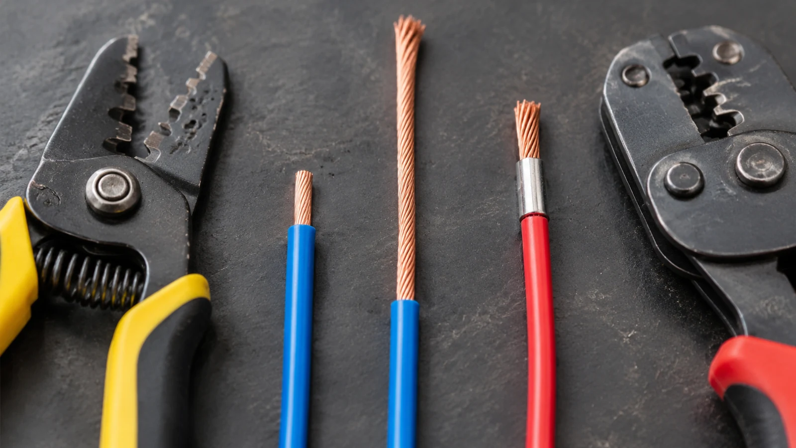
Stranded conductor needs the strands controlled before insertion. Twist the strands in the direction of the lay, keep the twist tight to the end, and use a ferrule where the block and the specification allow one. A conductor whose strands splay at the clamp has fewer strands carrying the current, and the ones outside the clamp are free to touch a neighbouring potential.
Conductor
Preparation before insertion
What goes wrong if skipped
Solid
Strip to length, insert straight, no twisting needed
Over-length strip stands proud of the clamp and closes the clearance to the next way
Stranded
Twist in the direction of the lay, keep the twist tight to the cut end
Splayed strands leave fewer strands carrying current and stray strands outside the clamp
Fine-stranded, bare
Twist tightly; insert only where the block is declared for bare fine-stranded conductor
Strands spread under clamp pressure and the joint relaxes under thermal cycling
Fine-stranded with ferrule
Crimp with a ferrule tool matched to the ferrule, then insert
Pliers crimps give an irregular section; the ferrule may not seat squarely or grip the strands
Rule 2: the input and output terminals do not share a torque value
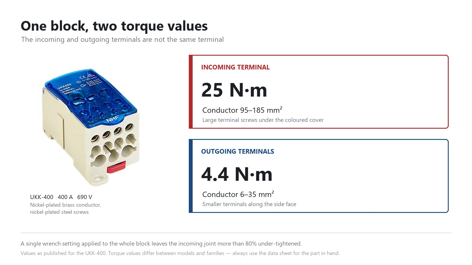
This is the rule that causes the most damage in the field, because it is invisible in the product photograph. A distribution block is not symmetrical. The incoming terminal is built to accept the full supply conductor; the outgoing terminals are built for the branch conductors. Different conductor range, different screw, different clamp geometry, and therefore a different torque.
On the UKK-400 the input terminal takes 25 N·m and the output terminals take 4.4 N·m. A technician who sets the torque wrench once and works along the block will under-tighten the input by more than 80 percent. The joint will feel secure, will pass a tug test, and will run hot from the first day of load.
Under-tightening is the more common error and the more dangerous one, but over-tightening has its own failure mode. Beyond the specified value the screw threads yield, the clamp body distorts, and fine strands crush. A crushed conductor joint often measures well when new and loosens faster under thermal cycling, because the deformed strands relax and the clamp pressure drops with them.
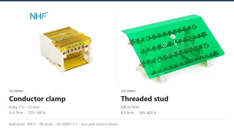
The practical consequence: a torque wrench set to one value for the whole panel is the wrong tool. Set it twice, once for the incoming terminals and once for the outgoing, and check the data sheet for the block in front of you rather than assuming that published ranges transfer between product families. Our C01 blocks run at 2–3 N·m on 125 A models while our UKK blocks run at 8.5 N·m on the same current — the clamping systems differ, and so do the values.
Rule 3: one clamp takes one rated conductor unless the sheet says otherwise
Multiple connection points at the same potential are normal. Multiple conductors inside one clamping unit are a different matter, and the distinction is where a lot of improvised wiring goes wrong.
Two outgoing ways at the same potential are two clamps, each rated for its own conductor. One clamp holding two conductors is a mechanical arrangement that has to be tested and declared. IEC 60947-7-1 treats the number and combination of conductors per clamping unit as a declared characteristic of the product, not as something the installer decides. The rated current of the block applies to the arrangement that was tested.
What that means on site:
If the data sheet lists a single conductor range for a terminal, one conductor per clamp is the rated arrangement.
Where a two-conductor combination is declared, it is declared for specific cross-sections, often smaller than the single-conductor maximum and sometimes not identical to each other.
Doubling up conductors to avoid a larger block does not double the current rating. It creates an arrangement with no declared rating at all.
The mechanical reason is straightforward. The clamp is designed to compress one conductor of a given shape against a known contact area. Two round conductors sit against each other as much as against the clamp, so the contact pressure each one receives is lower and less predictable, and the second conductor occupies space that the first one needed.
Where a branch circuit genuinely needs two conductors, the correct answer is a second way on the same block, a jumper to a neighbouring block, or a larger block with the right number of outputs. Our UKK and C01 ranges are specified by ways and by conductor range precisely so that the number of outgoing circuits is a selection decision rather than an assembly improvisation.
Rule 4: a ferrule changes what the clamp will accept
A ferrule adds a metal tube and a plastic collar around the conductor. That is what makes a fine-stranded conductor behave like a solid one at the clamp, and it is also why the largest bare conductor a block accepts is usually not the largest ferruled conductor it accepts.
The tube adds wall thickness, and the collar adds diameter behind the clamping zone. A 2.5 mm² fine-stranded conductor that enters a clamp bare may not enter the same clamp with an insulated ferrule. Published range data reflects this: terminal blocks commonly quote a wide fine-stranded range for bare conductors and a narrower one for conductors with ferrules. The Phoenix UT 2,5 is a published example, accepting 0.14–4 mm² fine-stranded bare and 0.14–2.5 mm² with ferrules.
Three practical points follow.
Check the range for the conductor you are actually installing, not the headline range. The headline figure is usually the bare-conductor maximum.
Match the ferrule to the clamp. Ferrules are not mandatory in every spring or push-in connection, and a ferrule is not suitable for every terminal. Where the block is declared for bare fine-stranded conductor, adding a ferrule can push the assembly outside its declared range.
Crimp with a proper tool. A ferrule crimped with pliers has an irregular section that may not enter the clamp squarely, and its grip on the strands is unverified. The crimp is part of the connection, not preparation for it.
Jumper bars have their own current limit
Bridging several ways together with a jumper bar is standard practice and it is well supported by the product system. What is often missed is that the jumper carries current too, and its rating is not the sum of the ways it links.
The current in a jumper is highest at the end nearest the feed and falls along its length as each way draws its share. A jumper linking ten ways fed from one end carries the full load of nine ways at its first section. That section, not the terminal, can become the limiting component.
Two rules keep this safe. Feed a long jumper run from the middle where the product allows it, which halves the current in each direction. And check the jumper’s own published rating against the current it will actually carry, rather than assuming that a bar rated for the block’s current can carry that current at every position along its length.
How to verify a connection instead of guessing
The usual field checks do not measure the thing that matters. Appearance tells you nothing about contact pressure. A tug test proves the conductor will not fall out, which is a much lower bar than proving the joint will stay cool.
Check
What it actually proves
What it misses
Visual inspection
Conductor is present and roughly in the right place
Clamp pressure, contact area, strand damage
Tug test
Conductor is retained mechanically
Resistance, and therefore heating under load
Torque wrench on the screw
The specified torque was applied
Whether the conductor was correctly prepared
Voltage drop under load
The joint’s resistance in service
Nothing significant at the joint itself
Thermal scan under load
Joints running hotter than their neighbours
Joints that are warm but not yet abnormal
Voltage drop is the most direct measurement available without dismantling the panel. Compare the drop across the joint with the drop across an equal length of the same conductor; a joint that shows a clearly higher figure is carrying more resistance than it should. Thermal scanning under real load is the practical routine check, and its value comes from comparison — the joint that runs hotter than its identical neighbours is the one to open.
Both checks need the panel under load. A dead test proves continuity, which is why an insulation and continuity check passes on a joint that will overheat the first time it carries its rated current.
The mistakes that show up most often
One torque setting for the whole block. The input terminal is under-tightened by a factor of two to five. This is the single most common cause of a hot incoming joint on a distribution block.
Stripping to a rule of thumb. Either the conductor does not reach the clamp or bare copper stands outside it, and neither is visible after the cover goes on.
Two conductors in one clamp. Done to avoid a larger block, it produces an arrangement with no declared rating.
Ferrule used outside the declared range. The conductor fits the clamp bare, so it is assumed to fit with a ferrule. It often does not.
Long jumper fed from one end. The jumper becomes the hottest part of the assembly while every terminal tests correctly.
Verification by tug. The joint is mechanically sound and electrically poor, and the panel is closed on it.
Reading the data sheet before the first conductor goes in
Every value in this guide comes from a published product characteristic, which means the information needed to wire a block correctly is available before the work starts. Four figures are worth pulling out of the sheet for each part number on the panel schedule: the strip length, the input torque, the output torque, and the conductor range for the conductor type being installed.
Our distribution blocks publish those values per model, including the split between input and output terminals, and the conductor ranges are given separately for rigid and flexible conductor so that the difference is visible rather than implied. The UKK range covers 80 A to 500 A at 690 V with impulse withstand from 22 kA to 51 kA; the C01 range covers 125 A and 160 A at 500 V with 20 kA; the SV range covers 100 A and 190 A at 500 V. Each model has its own torque pair, and the numbers do not transfer between families.
Terminal block wiring is decided by four values that are printed on the product data sheet and almost never checked on site: strip length, input torque, output torque and the conductor range for the conductor actually being installed. Get those four right and the joint runs cool. Get the torque wrong by assuming one value covers a whole block, and the joint runs hot from the day it is energised, with nothing in the panel to show why.
FAQ
What strip length should I use for terminal block wiring?
Use the strip length published for that specific block. It is a product characteristic, not a universal dimension, and published values for comparable 2.5 mm² blocks range from 9 mm to 12 mm. A procedure quoting one inch, or 25 mm, does not describe a rail-mounted terminal block.
Why are the input and output torque values different on the same block?
Because they are different terminals. The input accepts the full supply conductor and uses a larger screw and clamp; the outputs accept branch conductors. On our UKK-400 the input takes 25 N·m and the outputs take 4.4 N·m. Applying the output value to the input leaves it more than 80 percent under-tightened.
Can I put two wires in one terminal block clamp?
Only if the product data sheet declares that combination. IEC 60947-7-1 treats the number and combination of conductors per clamping unit as a declared characteristic. Two conductors in a clamp declared for one has no rating, and the current does not add up to double.
Do I need ferrules for terminal block wiring?
It depends on the block and the conductor. Ferrules improve the behaviour of fine-stranded conductor at a clamp, but they increase the outside diameter, and a conductor that fits bare may not fit with a ferrule. Check the published range for the ferruled conductor rather than the bare one.
How do I know a terminal connection is good?
Measure voltage drop across the joint under load, or compare its temperature against identical joints with a thermal camera. Neither a visual check nor a tug test measures contact resistance, which is the property that decides whether the joint heats up.
Both ranges are rated 500 V and IPk 20 kA, so the data sheet cannot choose for you. The difference sits at the input terminal: a conductor clamp with a published conductor range, or a stud that holds a cable lug.
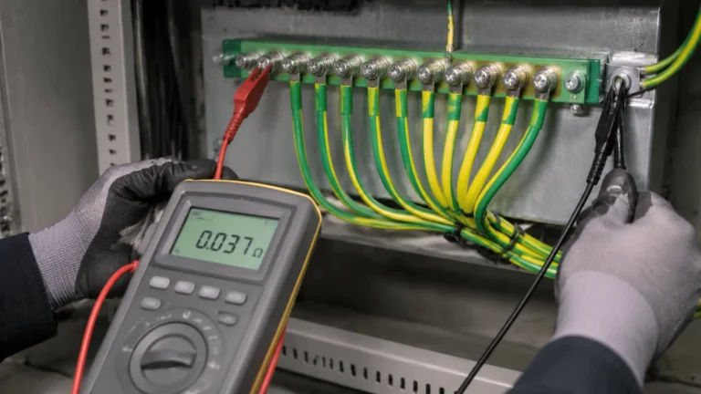
How to test earth continuity on a grounding bar: the dead test method, instrument and test current selection, acceptance values in ohms, and the parallel-path mistake that invalidates results.
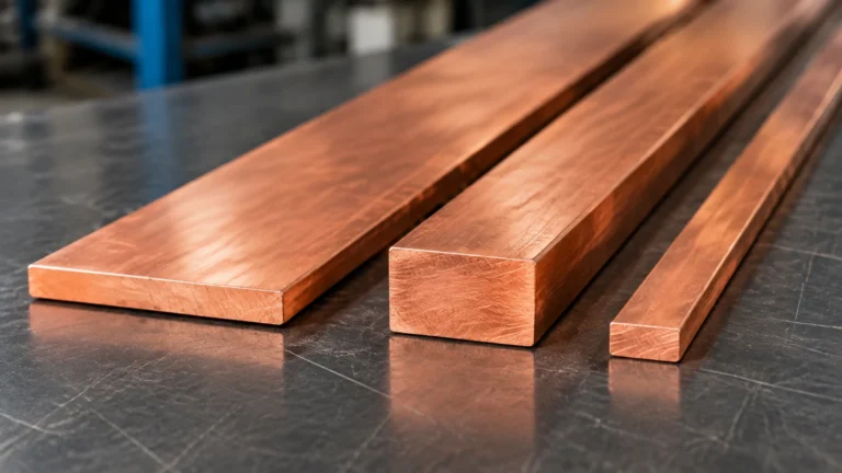
How to size a copper busbar: the current density formula, DIN 43671 ampacity tables, IEC 61439-1 temperature rise limits, short-circuit withstand and voltage drop.