C01 vs C02 Distribution Block: Clamp or Stud Decides the Choice
Published: Author: Rachel
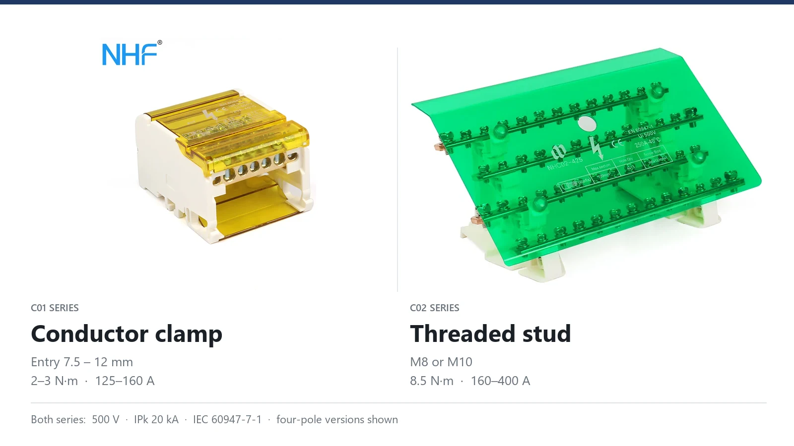
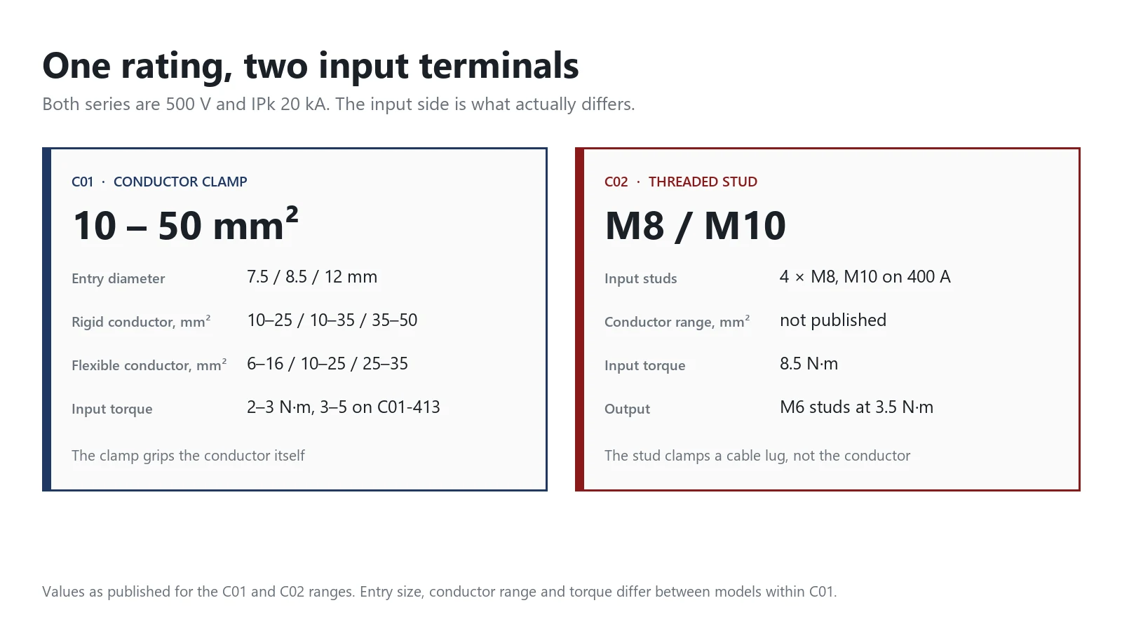
The C01 vs C02 distribution block question usually gets framed as a materials argument, brass against copper. That is not what separates the two ranges. Every block in both series is rated 500 V and IPk 20 kA, and every one of them ships with the same transparent polycarbonate cover. What changes is the input terminal: a screw clamp that grips the conductor itself, or a threaded stud that holds a cable lug.
Short answer: choose C01 when the incoming feeder is a bare or ferruled conductor up to 50 mm² and you want a published conductor range to design against. Choose C02 when the feeder already ends in a crimped lug, when the current is 160 A or more, or when the fault current has to pass through a bolted rather than a clamped joint. At 160 A the two answers overlap, and that overlap is where most specification errors happen.
The short answer
Both ranges are four-pole and two-pole DIN rail blocks that split one incoming feed into a row of outgoing circuits. They share the same rated voltage, the same impulse withstand, the same reference standard and the same cover material. Read down the data sheets side by side and the columns that differ are few, which is exactly why so many buyers fall back on price.
Property
C01 series
C02 series
Models in range
7 (two-pole and four-pole)
4 (four-pole)
Rated current
125 A, 160 A on C01-413
160 A, 200 A, 250 A, 400 A
Rated voltage / impulse withstand
500 V / IPk 20 kA
500 V / IPk 20 kA
Conductor
Brass
Purple copper
Fastener
Galvanised iron screws
Nickel-plated iron screws
Input interface
Screw clamp, 7.5 / 8.5 / 12 mm entry
M8 stud, M10 on the 400 A
Published input conductor range
10–25, 10–35 or 35–50 mm² by model
Not published — the stud takes a lug
Input / output torque
2–3 N·m, 3–5 N·m on C01-413
8.5 N·m input, 3.5 N·m output
Housing
PA66 V-2, PC/ABS V-0 on C01-413
PA66 V-2
Cover
Transparent PC
Transparent PC
Mounting
35 mm rail and screw fixing
35 mm rail and screw fixing
Two rows in that table carry the whole decision: the input interface and its published conductor range. Everything else follows from them — the tooling, the inspection routine, the panel depth, and to a large extent the price.
Both series are 500 V and IPk 20 kA, so the rating cannot decide
Start with the fact that makes comparisons collapse: a C01-207 rated 125 A and a C02-400A rated 400 A both declare IPk 20 kA. Tripling the current rating does not buy a single extra kiloampere of withstand at the block. IPk describes the peak current the block’s internal clearances and conductor geometry survived in a type test; it is not a number that scales with the amp rating printed on the front.
The practical consequence is simple. If the prospective fault current at the block is above 20 kA, moving up the range does not solve it. Nothing in either series will. The answer is upstream current limiting — a fuse or breaker with a low let-through — or a different class of equipment altogether. If the fault level is below 20 kA, then both series pass and the number stops being a selection criterion.
The same logic applies to the voltage rating. 500 V covers the three-phase low-voltage panels these blocks are built for, in both series, at every rating. Both ranges also cite the same reference standard, IEC 60947-7-1, which is where the declared conductor range and the rated values you are comparing come from.
That leaves the input terminal, where the two ranges diverge.
What the input terminal will accept
C01: a clamp with a published conductor range
Every C01 block opens a hole of a stated diameter and closes a screw clamp on whatever conductor is pushed into it. The data sheet publishes three numbers for that interface: the entry diameter, the rigid conductor range and the flexible conductor range. Those three numbers are the design constraint, and they differ model by model.
Model
Poles
Entry
Rigid input
Flexible input
Input torque
Size L×W×H (mm)
C01-207
2
7.5 mm
10–25 mm²
6–16 mm²
2–3 N·m
66 × 45 × 51
C01-211
2
8.5 mm
10–35 mm²
10–25 mm²
2–3 N·m
101 × 45 × 51
C01-215
2
8.5 mm
10–35 mm²
10–25 mm²
2–3 N·m
132 × 45 × 51
C01-407
4
7.5 mm
10–25 mm²
6–16 mm²
2–3 N·m
67 × 87 × 51
C01-411
4
8.5 mm
10–35 mm²
10–25 mm²
2–3 N·m
102 × 87 × 51
C01-415
4
8.5 mm
10–35 mm²
10–25 mm²
2–3 N·m
133 × 87 × 51
C01-413
4
12 mm
35–50 mm²
25–35 mm²
3–5 N·m
180 × 138 × 74
Two things in that table matter. The entry diameter tracks the conductor range, so a 7.5 mm hole and a 10–25 mm² range belong together; a 35 mm² conductor will not pass a 7.5 mm entry, and a 6 mm² conductor in an 8.5 mm entry has too little metal under the clamp to hold. And the flexible range is always narrower than the rigid one — 10–35 mm² rigid becomes 10–25 mm² flexible on the C01-411, because fine-stranded cable compresses under clamp pressure and the block is declared for less of it.
Within the range, the choice is mostly about entry size and body length. The two-pole C01-207 and the entry-level four-pole C01-407 share the 7.5 mm entry and the 10–25 mm² range. The C01-211 and C01-215 in two-pole, and the C01-411 in four-pole, move up to an 8.5 mm entry and a 10–35 mm² range, with more output positions as the housing lengthens.
What the clamp does well is accept the conductor you already have. A stripped 25 mm² cable goes straight in, is tightened to 2–3 N·m with a torque screwdriver, and is done. No lug, no crimping tool, no second part to order. For panels built from 10–35 mm² feeder cable, that is the whole appeal of the C01 range. If you are weighing a block against a plain terminal strip for the same joint, the comparison of distribution block and terminal block covers where each one belongs.
C02: a stud with a stud size, not a conductor range
The C02 series publishes something different at the input: a stud. Four M8 studs on the 160 A, 200 A and 250 A models, four M10 studs on the 400 A. Alongside the stud size the sheet gives one torque, 8.5 N·m, and no rigid or flexible conductor range at all.
That gap is not a missing data field. A stud terminal’s job is to clamp a cable lug flat against the conductor block; the conductor is defined by the lug the installer fits and the cable crimped into it. The block’s declared interface is the thread, and the thread is what it is rated for. Ask a supplier how many square millimetres a C02 takes and the data sheet answers with a stud size and a torque, not with a conductor range — because the range belongs to the lug.
In practice the incoming cable has to arrive with a lug already on it, or with a crimping tool and the right dies on site. A bare stranded conductor under a nut is not a substitute: the strands spread, the joint relaxes through the first thermal cycles, and the contact area you thought you had was never there. The bolted joint is excellent — a large, flat, high-pressure contact face — but only with a lug in it.
What changes on the bench
Tooling and sequence
The C01 input is tightened with a screwdriver or hex key at 2–3 N·m, within the range of a small torque screwdriver. The C02 input needs a socket and a torque wrench at 8.5 N·m, plus a crimping tool for the lugs before anything reaches the block. On a panel with forty branch circuits that changes the order of work: every feeder has to be terminated before the block is mounted.
There is a second tooling trap on the C02. Its input takes 8.5 N·m and its output studs take 3.5 N·m — a factor of 2.4 between two terminals on the same moulding. One wrench setting for the whole block will either under-tighten every input or over-tighten every output. The same pattern shows up across the range and is covered in more detail in the terminal block wiring rules, where the input and output torque split is the first principle rather than a footnote.
Installation of distribution blocks is work on conductors that will be live in service. It must be carried out by a qualified electrician in accordance with the local wiring regulations, and the torque values must come from the data sheet for the exact model in hand, not from a generic table.
What the inspector can see
Both series ship with a transparent PC cover, and in both cases the cover is meant to stay on. That matters for the C02 more than for the C01. On a stud joint the thing that fails is a lug sitting slightly proud, or a nut that was never run down; both are visible through a tinted cover and both are invisible once a solid lid is fitted. On a clamp joint the equivalent fault is a conductor not fully home, which is also visible through the cover but is more reliably caught by a pull check at the time of wiring.
Where the price difference comes from
With the ratings identical, the cost gap between a C01 and a C02 block comes from four things, and conductivity is the least of them.
The first is metal. C02 conductor parts are purple copper; C01 parts are brass. Copper costs more per kilogram, and the C02 blocks are physically much larger — 275 × 178 × 122 mm against 133 × 87 × 51 mm for a four-pole C01. That is roughly eight times the envelope, and the metal scales with it.
The second is machining. A stud is a turned thread that has to take 8.5 N·m repeatedly without stripping, paired with a nut and a nickel-plated finish; a clamp screw is a smaller, simpler part. The third is the terminal count — a C02 block carries forty M6 output studs with a nut each, all made, plated and assembled.
The fourth is the one buyers overestimate. Copper conducts at roughly 100% IACS and brass at roughly 28%, and it is tempting to read that as a 3.5× better block. But over the few centimetres of conductor inside a block, bulk resistance is a small fraction of the joint’s total; contact resistance at the terminal faces dominates, and that is set by contact area, pressure and surface condition. The same reasoning appears in the brass versus copper comparison: the gap is real, and it is not what makes a joint run hot.
So the honest summary of the price gap is: more copper, more machining, more parts, much more panel space. Not better conductivity at the joint. If a supplier justifies a premium purely on IACS percentage, the technical case is weak; if the premium buys a bolted joint that suits the feeder, it is worth paying.
The 160 A overlap: C01-413 against C02-160
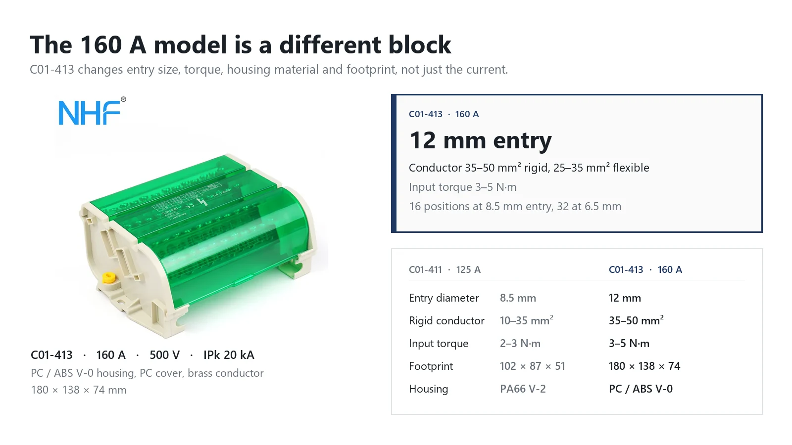
At 160 A the two ranges meet, and this is where the comparison stops being theoretical. Both blocks are four-pole, 500 V, IPk 20 kA, and both are rated 160 A. They are not interchangeable in any other respect.
C01-413
C02-160A
Rated current
160 A
160 A
Input
Clamp, 12 mm entry, 35–50 mm² rigid
Four M8 studs
Input torque
3–5 N·m
8.5 N·m
Output
16 positions at 8.5 mm entry, 32 at 6.5 mm
M6 studs, 3.5 N·m
Conductor
Brass
Purple copper
Housing
PC/ABS V-0
PA66 V-2
Envelope
180 × 138 × 74 mm
275 × 178 × 122 mm
The decision at this rating is made by the feeder, not by the block. If the incoming cable is 35–50 mm² and arrives bare, the C01-413 takes it directly at 3–5 N·m and needs nothing else. If the same 160 A feed arrives as a lugged cable — which is common on panel builders who crimp in the workshop — the C02-160A accepts it and the C01-413 does not, because a clamp cannot grip a lug.
Note also that C01-413 is not a scaled-up C01-411. The 125 A four-pole block is 102 × 87 × 51 mm with an 8.5 mm entry, a 10–35 mm² range, 2–3 N·m torque and a PA66 V-2 housing. The 160 A block is 180 × 138 × 74 mm with a 12 mm entry, a 35–50 mm² range, 3–5 N·m torque and a PC/ABS V-0 housing. Housing material, entry size, torque and footprint all change together. A panel laid out around the 125 A model will not accept the 160 A one in the same space.
Counting branch positions, not just poles
Pole count tells you how many phases the block distributes, not how many circuits come out — and that second number decides whether one block is enough. Every model has a ladder of outputs: a few large positions for sub-feeders, then a long row of small ones for branch circuits.
Model
Poles
Output positions as published
C01-207
2
2 × 10–25 mm², 10 × 2.5–10 mm²
C01-211
2
2 × 10–35 mm², 4 × 10–25 mm², 14 × 2.5–10 mm²
C01-215
2
2 × 10–35 mm², 4 × 10–25 mm², 22 × 2.5–6 mm²
C01-407
4
4 × 10–25 mm², 20 × 2.5–10 mm²
C01-411
4
4 × 10–35 mm², 8 × 10–25 mm², 28 × 2.5–10 mm²
C01-415
4
4 × 10–35 mm², 8 × 10–25 mm², 44 × 2.5–6 mm²
C01-413
4
16 positions at 8.5 mm entry, 32 at 6.5 mm
C02 (all)
4
M6 studs, listed as M6×40 on the sheet
The small rows catch people out. The 5.5 mm entry shared by the 2.5–10 mm² positions caps the branch conductor at 10 mm², so a plan needing 16 mm² outgoing cable cannot use those rows at all. That is why the C01-415 exists with 44 positions at 2.5–6 mm² for dense control wiring, while the C01-411 carries 28 positions up to 10 mm². Mostly 6 mm² or less outgoing, take the 415; a dozen 10 mm² branches, take the 411.
Choosing by ways alone often leads to a block that is electrically right and mechanically wrong. The selection logic for size, conductor and output layout is the same one set out in the UKK distribution block guide, and it transfers directly: count the largest outgoing conductor first, then count how many positions you need at each size, and only then compare models.
Space, rail and mounting
All eleven blocks in the two ranges mount on 35 mm DIN rail and also take screw fixing. That is the last thing the two series agree on.
The C02 envelope is identical across all four ratings: 275 × 178 × 122 mm for the 160 A, the 200 A, the 250 A and the 400 A. Moving from 160 A to 400 A costs no extra width, depth or rail length. What changes is the input stud, M8 to M10, and the rating on the label. For a builder who wants one cut-out and one mounting pattern across a product family, that is a real advantage and it is rarely mentioned on a data sheet.
Two cautions come with it. The 8.5 N·m input torque is the same on the M8 and the M10 stud, so do not assume the larger thread takes a higher figure. And a 122 mm tall block needs depth behind the rail; in a shallow enclosure the C01 range, at 51 mm tall, fits where a C02 will not. If the layout is still being drawn, the guide to DIN rail power distribution blocks covers how these blocks sit relative to breakers and cable ducts.
Six checks before you specify either series
Feeder conductor size. Measure the actual cable, not the design intent. If it is above 50 mm², neither series takes it directly; the C01 clamps stop at 50 mm² and the C02 needs a lug.
Is there a lug on the cable, or a crimping tool on site? Without one, the C02 is not installable. With one, it becomes the more robust joint.
Which torque tools are in the van? A 2–3 N·m screwdriver for C01, a socket and 8.5 N·m wrench for C02, and a second setting at 3.5 N·m for the C02 outputs.
Largest outgoing conductor. The 5.5 mm entry on the small rows stops at 10 mm², which rules out 16 mm² branches on every model except the C01-413.
Fault level at the block. Above 20 kA, change the upstream protection. No model in either range helps.
Enclosure depth and housing class. A C02 needs 122 mm of depth; only the C01-413 offers a V-0 housing if the enclosure specification calls for one.
Run those six in order and the answer usually falls out before you reach the price column. When it does not, the tie-breaker is almost always check two: whether the feeder arrives with a lug.
When neither series is the right answer
Three cases fall outside both ranges.
An incoming feeder above 50 mm² with no lug has nowhere to land. The C01 clamps end at 50 mm² on the C01-413; the C02 expects a lug. That is a lug problem, not a block problem — fit a lug and the C02-400 opens up.
A fault level above 20 kA is a protection coordination problem. Neither series is tested beyond IPk 20 kA, so the solution is upstream, not downstream.
And a single-phase distribution point with a modest current is usually better served by a single-pole block. The UKK range runs 80 A to 500 A in a single-phase body with a 690 V rating, and the selection logic for those is different again — more headroom on voltage, less on pole count.
Frequently asked questions
Can I put a bare conductor under the C02 stud?
No. A nut on bare stranded conductor does not produce a stable joint: the strands spread, the contact area is unpredictable and the joint relaxes as it heats and cools. Fit a crimped lug matched to the stud size, then tighten the nut to 8.5 N·m.
Is the C02 better because it uses copper?
It is better for a different reason. Copper conducts about 3.5 times better than brass, but over the length of a block that difference is small next to the resistance of the terminal contact itself. The C02 earns its price through the bolted joint, the higher ratings and the larger output array, not through the alloy.
Do both series fit the same DIN rail?
Yes. Both mount on 35 mm rail and both also offer screw fixing. The rail is the same; the depth and the footprint are not.
What torque do the C02 output studs need?
3.5 N·m, against 8.5 N·m at the input. The two figures must not be averaged or unified. On a four-pole unit that is forty joints at 3.5 N·m, each one a heat source if left loose.
Conclusion
The C01 vs C02 distribution block comparison is not a good-better-best ladder. They are two termination architectures that happen to share a voltage rating, an impulse withstand and a cover material. C01 clamps the conductor, publishes a conductor range, and tops out at 50 mm² on a compact 51 mm tall body. C02 clamps a lug on a stud, publishes a thread size instead of a range, and runs to 400 A in a single 275 mm envelope.
Choose on the feeder and on the fault level, in that order, and the price difference stops being the question. If the feeder is bare, ferruled and 50 mm² or less, the C01 range covers it with a published range you can design against. If it ends in a lug, or the current is 160 A and above, the C02 range is the one built for the joint you actually have. The figures quoted here come from the product pages for each model, not from a generic table.
Four rules decide whether a terminal block joint runs cool or overheats: the strip length the block specifies, the separate input and output torque values, one rated conductor per clamp, and the conductor range for the ferruled size.
How to test earth continuity on a grounding bar: the dead test method, instrument and test current selection, acceptance values in ohms, and the parallel-path mistake that invalidates results.
How to size a copper busbar: the current density formula, DIN 43671 ampacity tables, IEC 61439-1 temperature rise limits, short-circuit withstand and voltage drop.