DIN Rail Terminal Block Types: Which One Does Your Circuit Need?
Published: Author: Rachel
DIN rail terminal block types are not interchangeable, and picking the wrong one only shows up months later, when a panel fails inspection or a circuit will not isolate. The decision starts with a simple question: what does this circuit have to do? Once you answer that, the type narrows quickly, and the mechanical and electrical specifications become a checklist rather than a guess.
This guide works through the terminal block families by circuit function first, then maps each one to a product you can order. Every dimension, current figure and torque value below comes from our own published product data.
Start with the circuit function, not the housing colour
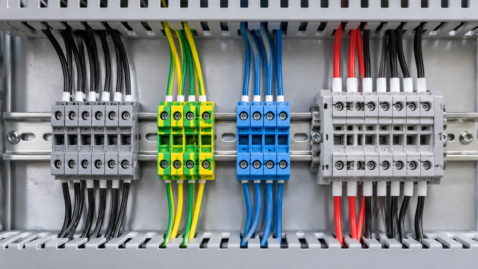
A DIN rail terminal block is a mounting solution and a connection point at the same time. The rail itself carries no current; it is a standardised 35 mm steel or aluminium strip that holds devices in place. What makes a block the right one is in its internals and its marking. Before you read a single datasheet, list the circuits on your drawing and assign each one a job:
Pass current through. Incoming and outgoing conductors need joining. A feed-through terminal.
Carry protective earth. The conductor must reach a defined earth path, usually by bonding to the rail. A PE terminal block.
Protect a branch. Overcurrent protection with the fuse reachable from the panel face. A fuse terminal block.
Break the circuit deliberately. A visible break for testing or maintenance. A disconnect terminal.
Fit more circuits into less rail. Two or three levels stack in one footprint. A multi-level terminal.
Land 24 V DC field signals. Several conductors per device plus a status indicator. A sensor or actuator terminal.
Split one supply into many. One incoming conductor feeds several outgoing circuits. A power distribution block.
Only after the job is fixed does the mechanical choice matter: how the block mounts, what colour it is, how many ways it has, and what conductor section it accepts. Worked through in order, these DIN rail terminal block types give you a part number rather than a guess.
The eight DIN rail terminal block types at a glance
Type
Circuit job
How to identify it on the rail
Check before ordering
Feed-through
Joins incoming to outgoing conductor
Plain housing, one or two wire entries per side
Conductor range, rated current
Protective earth (PE)
Connects the protective conductor to the earth path
Marked PE, with a metal contact foot onto the rail
PE approval, rail bonding
Fuse
Accessible branch-circuit protection
Wider housing with a fuse holder in the face
Fuse format, breaking capacity
Disconnect / knife
A deliberate, visible break in the circuit
Lever or knife mechanism in the front
Switching duty, test plugs
Multi-level
Stacks two or three circuits in one footprint
Taller housing, two or three rows of entries
Level marking, isolation
Sensor / actuator
Organises 24 V DC field I/O wiring
Several conductors per way, often an LED window
PNP or NPN, commoning
Multi-conductor / distribution
Shares one potential across several ports
Several outputs from one input
Commoned paths, path rating
Component carrier
Holds a diode, LED, resistor or varistor
Extra wide body with a component bay
Component type and rating
One point is worth stating plainly. Pluggable is not one of the eight. It describes how a module separates from its base for service, and a pluggable terminal can still be feed-through, fused or multi-level. Keep the interface choice separate from the circuit job.
Feed-through terminals: the default for point-to-point wiring
A feed-through terminal is the most common block in any control cabinet. It carries a conductor from one side to the other through an internal metal path, held by a screw, a spring cage or a push-in spring. For ordinary point-to-point power, control and signal wiring it is the right default: there is no reason to pay for a specialised function unless the circuit needs one.
Three parameters decide whether a given block works in your panel. Rated current is the continuous current the internal path carries, not the rating of the breaker feeding it. Rated cross-section is the conductor range the clamping unit accepts: a block that takes 10 to 35 mm² rigid will not accept 2.5 mm² stranded without a ferrule. Short-time withstand current is the peak the path survives, usually expressed as Ipk in kA.
Our screw-type blocks are rated to IEC 60947-7-1, which covers screw-type and screwless clamping units for round copper conductors from 0.2 mm² to 300 mm², in circuits up to 1000 V AC and 1500 V DC. It also sets the dielectric strength, voltage drop, temperature rise and pull-out force requirements. The three parameters above are model-specific: check them on the datasheet for the exact block rather than carrying a figure across from another product.
Protective earth terminals: the ones that bond to the rail
A PE terminal block is not a feed-through block with a green housing. It has a metal contact foot that makes a direct electrical and mechanical connection to the DIN rail, and the rail is bonded back to the panel’s main earthing system. That foot is the entire electrical function, and it is why the block is listed under a separate product standard.
PE terminal blocks fall under IEC 60947-7-2, fuse terminal blocks under IEC 60947-7-3, and PCB terminal blocks under IEC 60947-7-4. If a supplier quotes a terminal block without naming a part of the IEC 60947-7 series, ask.
Our PE-side products are colour-identified at the fixing part rather than relying on the housing alone. The NHA04-E earth bar with green fixing part carries a green fixing element, and the NHA27-E screw terminal grounding bar with cover gives you the earth connection with a transparent cover over the screws. For a fully enclosed version, our a fully enclosed variant keeps the conductors completely enclosed.
Note the deliberate difference from the neutral side. A PE block and a neutral block may sit next to each other on the same rail, but they must not be the same block. Our NHA04 neutral bar with blue fixing part is colour-marked blue to keep the two visually distinct, which is the simplest way to stop a miswire during panel build. The wiring rules behind that separation are covered in our guide on putting a ground wire on a neutral bar, and the difference between the two devices in neutral bar versus ground bar.
Fuse terminals and disconnect terminals
These two are grouped together because both are wider than a standard block, but they solve different problems and are governed by different standards.
Fuse terminal blocks
A fuse terminal block integrates a fuse carrier into the terminal, so protection sits at the point of connection rather than in a separate holder. The benefit is serviceability: the fuse changes without disturbing the wiring around it. The parameters that matter are the fuse format, the breaking capacity, and whether a blown fuse is visible from outside the cabinet. IEC 60947-7-3 sets out the safety requirements for this block type.
Disconnect and knife-disconnect terminals
A disconnect terminal creates a deliberate break in the circuit without removing any conductor, which is what lets a technician verify a circuit is dead before touching it. For current transformer secondary circuits there is a more specialised variant, the test-disconnect terminal, which provides a controlled shorting sequence so the CT is never left open-circuited.
Choose on permitted duty rather than on appearance. A disconnect terminal intended for signal isolation is not necessarily rated for load switching, and the manufacturer data will say which duty the mechanism is approved for.
Multi-level terminals: more circuits per millimetre of rail
When rail space is the binding constraint, a multi-level terminal stacks two or three independent circuits vertically, using one footprint instead of two or three. On a control cabinet with dozens of 24 V DC sensor circuits, this is often the difference between fitting the devices inside the enclosure and running out of backplate.
Two things decide whether a multi-level block saves space. Wire access: on a stacked block the conductor has to reach the lower level, which means a deeper enclosure and more bend radius. And level identification, because a miswired lower level is hard to reach and easy to miswire.
Where space is genuinely critical, our NHA29 eight-way insulated strip block takes a different route: it puts eight ways into a single insulating housing, 173 mm long at 16 mm² and 270 mm at 70 mm², so eight conductors share one body instead of eight separate pieces of plastic.
Sensor and actuator terminals
Field I/O wiring is where terminal blocks earn their keep in a PLC cabinet. A three-wire sensor needs a signal, a supply and a return, often with a status indicator. A sensor terminal block packages all of that into one way, so the cabinet keeps a consistent grid rather than a mix of singles and specials.
The critical parameter here is not current, it is sourcing and sinking. A PNP sensor switches the positive side of the supply and a NPN sensor switches the negative side, so a terminal block with an LED wired for one convention will read backwards on the other. Also check the commoning arrangement against your field wiring, and whether shield termination has a dedicated way to leave the block, because improvised shield connections inside the cabinet are a common source of noise problems that end up blamed on the PLC.
Power distribution blocks are a different category
A distribution block is not a terminal block with more ways. The topology is different: one incoming conductor feeds many outgoing paths, and the block is rated on the current in that common path and on the fault withstand of the whole assembly. A terminal block that passes each conductor through separately has no shared path to rate.
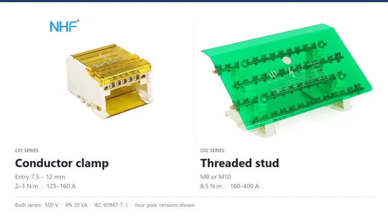
Our range runs from 80 A to 500 A. The UKK-160A single phase distribution block and the C01-407 125A four phase distribution block cover the mainstream panel sizes. The C01-407 is rated 500 V and 125 A, with a 20 kA impulse withstand, and accepts 10 to 25 mm² rigid conductors on the input side while the output side takes 2.5 to 10 mm² through a separate 5.5 mm entry. Torque on that unit is 2 to 3 Nm.
At the top of the range the construction changes completely. The C02-400A four phase distribution block uses a purple copper conductor with nickel-plated iron screws and M10 stud connections rather than small wire screws, tightened to 8.5 Nm on the input side.
The gap between those two constructions is not a matter of price tiers. Both are rated 500 V and IPk 20 kA, and the real difference sits at the input terminal: the C01 range clamps a conductor of a published size, the C02 range clamps a cable lug on an M8 or M10 stud. C01 vs C02 distribution block sets the conductor ranges, stud sizes and torque values side by side.
Once the circuit function is settled, mounting is the next axis that changes the part number. Three arrangements are in use and they are not interchangeable.
Mounting method
How it is fixed
Typical bar section
Trade-off
Screw fixation
Bolted to the backplate through standoffs
1.5 × 15 to 3 × 25 mm
Lowest cost, no rail needed, but uses backplate area
DIN rail snap-on
Clips onto a 35 mm top hat rail
Link bars in brass, 100 A class
Fast to reconfigure, but the rail costs money and takes depth
Bridge type
A continuous bar with conductors on raised positions
The third decision: colour identification, and the green-yellow rule
Colour is the fastest way to identify a function on a crowded rail, and it is standardised under IEC 60445. Green and yellow is reserved for protective conductors, blue identifies the neutral. North American practice under NEMA uses a different phase colour set, which is one reason a panel built to one convention should not be opened by someone working to the other.
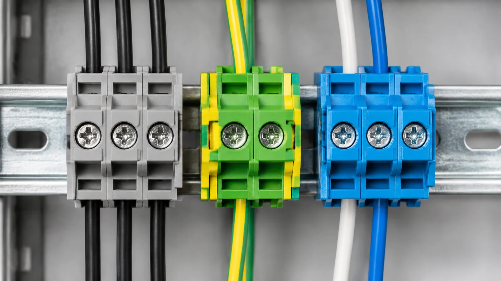
There is a rule that catches out experienced installers, and it is written into the product standard. IEC 60947-7-1 clause 7.1.4 states that the green-yellow colour combination is not permitted for marking terminal blocks. The reason is straightforward: green-yellow on a terminal means protective earth, and if every terminal could carry that colour, a green-yellow terminal could be mistaken for a PE connection when it is not one.
This applies to through terminal blocks under IEC 60947-7-1. It does not apply to ground conductor rail-mount terminal blocks approved under IEC 60947-7-2, which are permitted to be green-yellow because they are specifically PE products.
The fourth decision: ways, conductor section and physical size
Once function, mounting and colour are settled, the sizing is arithmetic. Three numbers determine whether a block physically fits: the number of ways, the maximum conductor section per way, and the overall length on the rail. Our A29 eight-way strip block shows how they interact: the same eight ways are available from 16 mm² to 70 mm², and as the section goes up the body gets longer and wider.
Model
Ways
Max conductor section
Length
Width
A28/16
8
16 mm²
173 mm
24 mm
A28/25
8
25 mm²
205 mm
27 mm
A28/35
8
35 mm²
250 mm
33 mm
A28/50
8
50 mm²
260 mm
35 mm
A28/70
8
70 mm²
270 mm
38 mm
The pattern holds across the range: a higher conductor section means a longer body, so count the length rather than the number of blocks when you work out how many fit, and add the end stops and separation pieces at both ends.
For a single large conductor, our NHA30 series gives one way per housing with a length that tracks the section directly, from 16 mm at 16 mm² to 120 mm at 120 mm². The A29 strip block covers the multi-conductor side.
Temperature and material decide the last few percent of the order
The housing material sets the operating temperature range, and this is where a nominally identical part number can fail on a hot panel. Our blocks fall into three groups.
PA66 nylon with UL94V-2 rating. Used across the A29 and A30 series, operating from −30 °C to 110 °C at 250 to 450 V. The general-purpose choice and the widest temperature band we offer.
PC polycarbonate. Used on the A28 colourised holder series, rated −40 °C to 85 °C, with better low-temperature behaviour than PA66.
PP polypropylene. Used on the A21 series, rated −40 °C to 65 °C, with good chemical resistance but a narrower upper temperature limit.
All three families carry CE and RoHS certification, and the relevant performance standard is IEC 60947-7-1 with a rated voltage range of 250 to 450 V.
The temperature difference is not academic. A block rated to 65 °C in a panel sitting in a 50 °C ambient has only 15 K of headroom, and current capacity falls as temperature rises — the same derating logic that applies to every other component in the cabinet.
Five mistakes that come back to the same panels
Choosing by housing colour. A green housing does not make a block a PE terminal, and the absence of green does not mean a block is safe for earth. Look for the PE marking and the metal foot.
Ignoring the torque figure. The torque specified for the clamping unit keeps contact resistance stable for the life of the panel. Our C01 series runs 2 to 3 Nm and the C02 series 8.5 Nm on the input side, and those figures are specific to those units. Under-torquing gives a loose contact that heats up; over-torquing strips the thread.
Leaving no expansion room, and mixing standards. Panels get modified, so a rail with every position occupied costs far more to extend later than one with two spare positions and a separator left in place. Blocks from different standards also do not necessarily share an accessory system, so a bridge, a test plug or an end stop from one family may not fit another.
Frequently asked questions
Can I use a green-yellow marked terminal block for protective earth?
Not on a through terminal block. IEC 60947-7-1 clause 7.1.4 prohibits the green-yellow combination for marking terminal blocks so it cannot be confused with a protective earth connection. Ground conductor rail-mount terminal blocks approved under IEC 60947-7-2 are the specific case where it is permitted. On a standard block, mark the connection with the IEC 60417-5019 protective earth symbol or the letters PE.
How do I know how many ways I need?
Count the conductors that land on that group in the wiring schedule, then add the positions you want to reserve for future circuits. Do not count devices, count conductors. Our neutral bar size chart sets out the full sizing sequence.
Does the current rating of the terminal block need to match the breaker?
It needs to be at least the load current, and checked against the conductor section you are actually using. A block rated 125 A fed by 6 mm² copper is limited by the cable, not by the block. Our brass versus copper neutral bar comparison covers how conductor material changes the practical outcome.
Are DIN rail terminal blocks suitable for DC applications?
The rated voltage range matters more for DC than for AC, because a DC arc does not self-extinguish at a current zero the way an AC arc does at 50 Hz. Our screw terminal blocks are rated 250 to 450 V, and the standard distinguishes rated voltage from rated impulse withstand voltage, which is where the AC and DC difference shows up in the data.
Can I mix terminal block families on the same rail?
Mechanically, blocks on the same rail profile fit side by side. The practical constraints are accessory compatibility, depth, and the end stop and separator sizes matching the housing. If you want one accessory system across a panel, specifying a single family for the whole rail is safer.
How do I tell a PE terminal block from a neutral one in the field?
Three checks in order. Look for the PE marking or protective earth symbol on the housing. Look for the metal contact foot that bonds the block to the rail, which a neutral block does not have. And check the colour of the fixing part or holder: on our range PE products carry a green fixing element and neutral products a blue one, so the identification survives even when the housing colour is not visible from the front.
Conclusion
Function, mounting, colour and section are four independent decisions, and the part number you order falls out of them. The order matters: change the mounting method after you have fixed the function and you will be re-ordering blocks.
Our range covers screw-fixed, bridge type and DIN rail mounted arrangements in brass, with way counts from 3 to 20 and conductor sections from 1.5 × 15 mm to 120 mm². Send a panel schedule and we will specify the terminal block line items against it.
Both ranges are rated 500 V and IPk 20 kA, so the data sheet cannot choose for you. The difference sits at the input terminal: a conductor clamp with a published conductor range, or a stud that holds a cable lug.
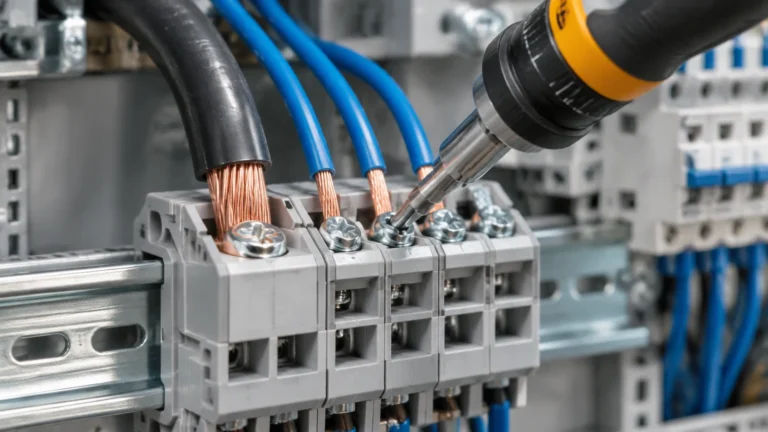
Four rules decide whether a terminal block joint runs cool or overheats: the strip length the block specifies, the separate input and output torque values, one rated conductor per clamp, and the conductor range for the ferruled size.
How to test earth continuity on a grounding bar: the dead test method, instrument and test current selection, acceptance values in ohms, and the parallel-path mistake that invalidates results.