DIN Rail Sizes Explained: TS35 vs TS15 vs G32 Guide
Published: Author: Rachel
This guide sets out the DIN rail sizes defined in EN 60715 and IEC 60715, gives the dimensions and hole patterns for the rails we manufacture, and works through the practical questions that come up when you specify a rail for a panel.
Quick answer: almost every DIN rail you will meet in a control cabinet is the 35 mm top hat profile, commonly written TS35 or TH35, measuring 35 mm wide by 7.5 mm deep. The other profiles exist but are not interchangeable with it: a TS15 is 15 mm wide and a device designed for TS35 will not seat on it, and a G32 is an asymmetric 32 mm section with a completely different foot geometry.
The width is not the whole story, and it is not the part that catches people out. Two rails can both be 35 mm wide and still behave differently once they are on the backplate, because the depth and the mounting hole pattern decide how the rail is fixed and how much it flexes under a heavy device. A 7.5 mm deep rail is the standard. The 15 mm deep variant of the same top hat profile uses the same slots and takes the same devices, but it resists bending over long unsupported spans and leaves more room behind for wiring.
A DIN rail is a standardised metal profile that electrical and control devices clip onto. The name comes from the Deutsches Institut für Normung, the German standards body that first defined the profile, but the dimensions are now set internationally in EN 60715 and IEC 60715.
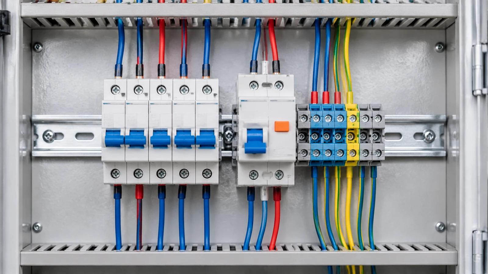
Before standardised rail, every device in a panel needed its own bracket and its own drilled fixing. A standard profile changed that. Each device has a hook at the top of its mounting clip and a spring latch at the bottom: you hook the top over the rail, push the latch home, and the device is held. To remove it you pull the latch down with a flat screwdriver and tilt it off. Because devices slide along the rail rather than being screwed to a plate, a cabinet can be laid out, tested and re-arranged without drilling a single new hole.
That interchangeability is the entire point, and it is also why rail profile matters more than it first appears. A rail is not a piece of metal; it is a defined mechanical interface. When the interface does not match, the device either does not clip on at all, or it clips on and works loose.
The three DIN rail sizes defined in EN 60715
The standard defines three families of rail that account for the overwhelming majority of installations. The names vary between manufacturers, which is a frequent source of confusion when cross-referencing a supplier catalogue against a datasheet, so the dimensions are the reliable identifier.
Compact enclosures, small relays, building automation controllers
G32
G section, asymmetric
32 × 15 mm
EN 50035
Heavier devices, legacy meter panels, industrial machinery
Two things follow from this table that are worth stating plainly, because both are routinely mistaken.
The two TS35 depths share the same slot geometry, so devices interchange between the 7.5 mm and 15 mm versions without modification. The deeper rail simply gives more clearance behind it for wiring and more stiffness.
TS15 and G32 use different foot geometries. A TS35 device will not seat on a TS15 rail, and a TS15 terminal block will not grip a TS35 rail correctly. These are not smaller and bigger versions of the same thing; they are different interfaces.
Reading a rail specification: the four numbers that matter
A rail is specified with four figures, and each one answers a different question. Getting the width right but the hole pattern wrong is the most common way to end up with a rail that cannot be fixed to the backplate you have.
Specification
What it tells you
Why it matters
Width
35 mm for TS35
Determines which devices clip on
Depth
7.5 mm standard, 15 mm deep
Stiffness over long spans and clearance behind the rail
Thickness
1.0 mm, 1.5 mm or 2.0 mm
Load capacity and resistance to bending
Hole pattern
Hole diameter and slot length
Determines which screws and fixings will pass through
The hole pattern is the one buyers most often miss. A rail is not drilled to a universal pattern. The slots are there so the rail can be fixed at any position along its length with a machine screw into a tapped backplate hole, but the slot width and the screw diameter are fixed by the manufacturer. If your backplate has 6.2 mm holes and you buy a rail slotted for 4.2 mm screws, the fixings will not pass through it.
Our rail specifications
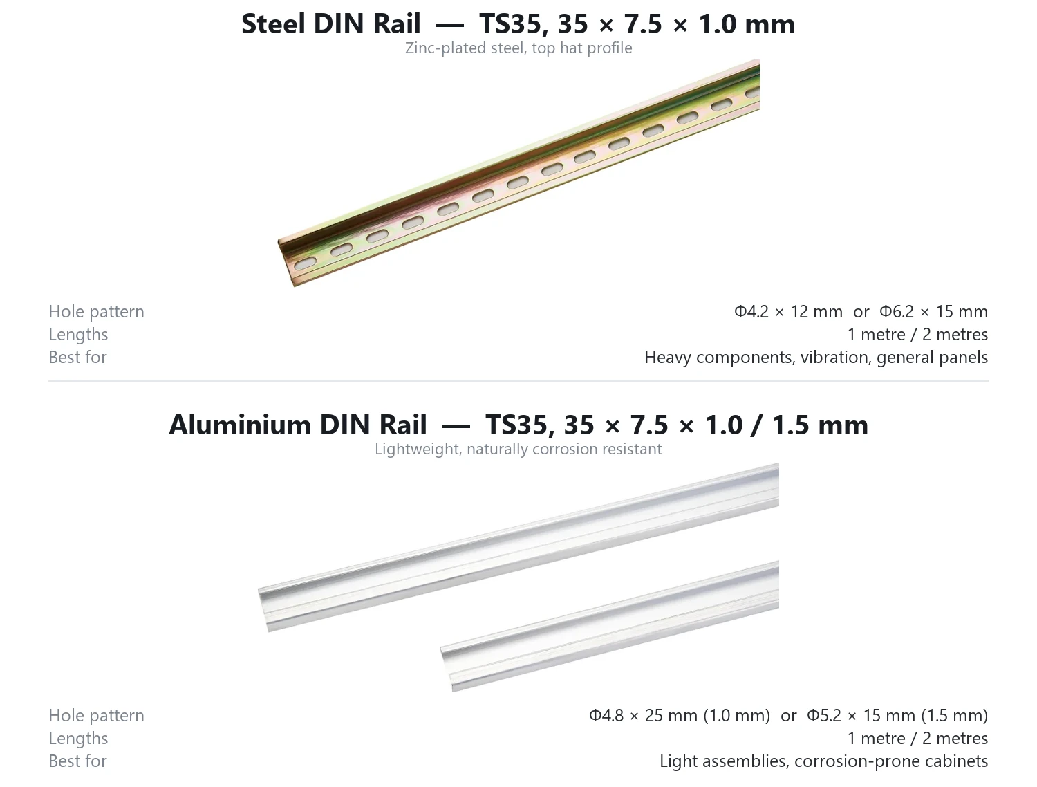
We manufacture the 35 mm top hat profile in two materials and, for each material, in two thicknesses with different hole patterns. All are supplied in 1 metre and 2 metre lengths.
All five variants are the same 35 mm top hat profile, so any TS35 device fits any of them. What changes between them is how the rail is fixed to the backplate and how much load it carries before it starts to bow.
Steel or aluminium: which material to specify
Both materials are 35 mm top hat and both take the same devices. The choice comes down to weight, environment and load.
Factor
Zinc-plated steel
Aluminium
Weight
Heavier
Around a third lighter for the same profile
Corrosion resistance
Zinc layer with passivation; adequate in dry indoor enclosures
Naturally corrosion resistant, no coating required
Stiffness
Higher for the same thickness; resists bending better
Lower; benefit from the 1.5 mm variant on longer runs
Heavy or vibrating loads
Preferred
Not recommended without extra support
Cost
Lower
Higher per metre
For most control panel work, steel is the default and the right answer. Aluminium earns its place in two situations: where the cabinet is in a genuinely corrosive environment, such as a washdown area or a plant room with aggressive cleaning chemicals; and where the panel itself has to be light, such as a battery or mobile enclosure. The trade-off is that aluminium is softer, so a heavy device on a lightly supported aluminium run can work the rail loose over time.
Depth and thickness: when 7.5 mm is not enough
The 7.5 mm deep TS35 profile is standard and it is what you should specify unless something forces you off it. There are two things that do.
The first is a long unsupported span. Rail is stiff in bending but not infinitely stiff, and a run with fixings at 400 mm intervals carrying a row of heavy devices will visibly bow between them. The bow is not only ugly; it puts the devices under side load that the clip was never designed to carry, and it is a common reason terminals loosen in service. The remedies are, in order of preference, the 15 mm deep profile, closer fixing centres, or both.
The second is cable routing behind the rail. A 7.5 mm deep rail leaves almost no space behind it, so the wiring has to come off the devices and out to the side. If your design routes large numbers of conductors behind the rail, the 15 mm version gives you the room to keep them there instead of bunching them in the wiring duct.
Thickness works the same way. A 1.0 mm rail is adequate for a row of terminal blocks. A 1.5 mm or 2.0 mm rail carries more load over the same span. The increments are not subtle: going from 1.0 mm to 1.5 mm raises the section by half, and the load a rail can carry between fixings goes up considerably with it.
How to mount DIN rail correctly
Mounting a rail is straightforward, but the details are what separate a panel that stays tidy from one that gets worked on repeatedly.
Fix the rail to a rigid backplate
Use a rigid mounting plate, not a sheet of thin steel or a piece of perforated sheet. The rail is only as stiff as what it is fixed to, and a flexible backplate turns a well-supported rail into a poorly supported one.
Space the fixings correctly
Support the rail at regular intervals, typically every 100 to 200 mm, and always fix near both ends and adjacent to any heavy device. Where you must span a longer distance, either step up to the 15 mm deep profile or bring the fixing centres in. This is the single most common cause of rail-related complaints, and it costs nothing to get right at build time.
Choose the fixing to suit the hole pattern
Match the screw to the slot. Our 4.2 mm and 5.2 mm slotted rails take M4 machine screws; the 6.2 mm rail takes M6. On a tapped backplate the screw goes straight in. On an untapped plate, use a nut and washer behind. Either way the screw should sit squarely in the slot so the load is taken by the metal rather than by the slot edges chewing.
Cut and deburr properly
Cut with a fine-tooth hacksaw or a dedicated rail cutter, and always deburr the cut end and the slots. A sharp edge left on the profile will shave the plating where devices are slid on, and it is a cut hazard for anyone working in the enclosure.
Fit end stops and consider the earth path
End stops at both ends of a row stop devices sliding off the rail and stop the row creeping under load. And if the rail itself is intended to form part of the protective earth path, remember that many rails are supplied with a passivation or coating that will interrupt continuity: make sure there is a reliable metal-to-metal bond at the earth point rather than relying on the rail coating.
Before ordering anything, measure the rail you already have. The check takes a minute and eliminates the most common ordering error, which is buying a rail that does not match the hole pattern of the backplate it has to fit.
You need three measurements: the width across the face of the rail, which gives you the profile, the depth from the face to the back of the section, which distinguishes the 7.5 mm from the 15 mm version, and the slot dimensions, which determine the screw. A caliper covers all three. If the rail is already installed, the devices on it are a quicker reference than the rail itself: a TS35 device means a 35 mm profile, and the device footprint tells you how much of the slot is covered.
On an installed rail, the depth can be read directly from the back: leave the rail in place and measure the gap between the back of the section and the mounting plate. That gap is the depth. It is a quick check, and it is worth doing before you order replacement rail for a cabinet that was built by someone else.
Matching the rail to what mounts on it
The rail and the devices are chosen together, and it is worth being deliberate about the combination.
Most of the DIN-mounted products in our range are built for the 35 mm profile, which is stated in their specifications. Our NHA08 neutral bar mounts on 35 mm DIN rail with screw fixation and carries up to 450 V, and the NHA11 neutral bar link is a 35 mm rail mounted assembly rated from −30 °C to 110 °C. The NHA15 neutral bar link offers the same 35 mm rail mounting in a higher current rating. Where you need a rail-mounted device that handles higher current, our UKK 160A distribution block and the UKK series distribution blocks and the wider distribution block range cover from 80 A to 500 A on the same mechanical interface.
If you are building out a panel rather than replacing a single device, the DIN rail category collects the rails, the rail-mounted terminal blocks and the neutral and ground bar assemblies that sit on them, so you can check compatibility across the whole row rather than part by part.
Frequently asked questions
What is the standard DIN rail size?
35 mm wide by 7.5 mm deep, the top hat profile. This is what the term means when someone says DIN rail without qualifying it, and it is the profile used by the overwhelming majority of terminal blocks, breakers, relays and contactors in industrial panels. The 35 × 15 mm deep version shares the same slot geometry and takes the same devices.
Are TS35 and TH35 the same thing?
Yes. TS and TH are the designations used in the standard for the top hat section, and manufacturers use them interchangeably for the same 35 mm profile. Both refer to 35 × 7.5 mm unless the datasheet says otherwise. Some supplier catalogues use entirely different naming schemes, which is why matching on dimensions is safer than matching on a name.
Can I use a 15 mm deep rail with the same terminal blocks?
Yes, if the blocks are TS35 type. The 15 mm deep version has the same slot geometry, so devices interchange without modification. The extra depth gives more room behind the rail for wiring and more resistance to bending. A TS15 device, however, will not seat on a 35 mm rail at all, because the mounting foot geometry is different.
How far apart should DIN rail fixings be?
Every 100 to 200 mm is the normal range, with a fixing near each end of the run and one adjacent to any heavy component. Where the span has to be longer, use the 15 mm deep profile or bring the fixings closer. A rail that bows between fixings is the most common cause of terminals working loose after a period in service.
Is aluminium DIN rail as strong as steel?
No, not for the same thickness. Aluminium is around a third lighter and does not corrode, which makes it the better choice in washdown areas and aggressive environments. But it is softer, so under a heavy device or sustained vibration a lightly supported aluminium run can deform where a steel run would not. For heavy or vibrating loads, use steel, or use the thicker 1.5 mm aluminium variant with closer fixings.
What size screw do I need for a slotted DIN rail?
It depends on the rail. Our 4.2 mm and 5.2 mm slotted rails take M4 machine screws, and the 6.2 mm rail takes M6. Check the slot dimensions against the fixing you intend to use before you cut the rail to length, because it is much easier to change the screw at that point than after the backplate is assembled.
Summary
The 35 mm top hat profile at 7.5 mm deep is the default, and most specifications should simply say TS35 or TH35. The parts of the specification that actually cause problems on site are the depth, the thickness and the hole pattern, not the width. Specify the hole pattern against the fixings you have, step up to the 15 mm deep profile for long spans or heavy devices, and space the fixings at 100 to 200 mm. Get those three right and the rail will not be the part of the panel that causes you trouble.
We supply the 35 mm top hat profile in zinc-plated steel and in aluminium, in 1 metre and 2 metre lengths, with hole patterns covering the common backplate fixing standards. If you need a length or hole pattern that is not in the range, send us the drawing and we will quote it. For the full range, see the DIN rail category or the steel rail and aluminium rail product pages.
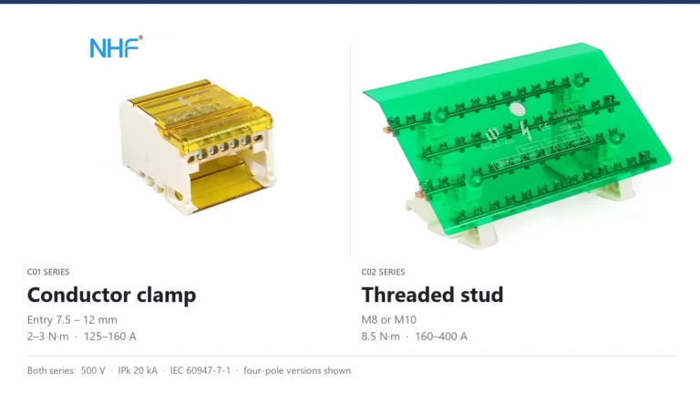
Both ranges are rated 500 V and IPk 20 kA, so the data sheet cannot choose for you. The difference sits at the input terminal: a conductor clamp with a published conductor range, or a stud that holds a cable lug.
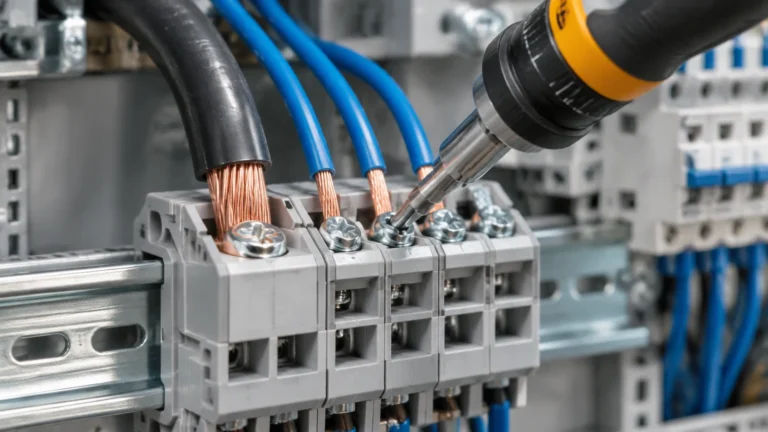
Four rules decide whether a terminal block joint runs cool or overheats: the strip length the block specifies, the separate input and output torque values, one rated conductor per clamp, and the conductor range for the ferruled size.
How to test earth continuity on a grounding bar: the dead test method, instrument and test current selection, acceptance values in ohms, and the parallel-path mistake that invalidates results.