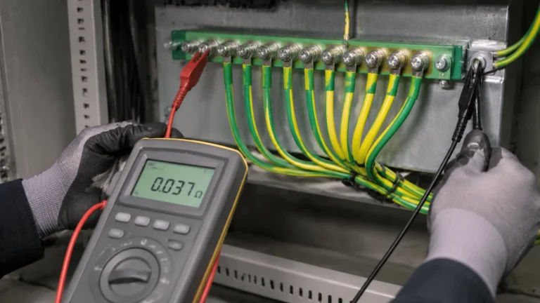
Can You Put a Ground Wire on a Neutral Bar? What the Codes Say
Published: Author: Rachel
The ground wire on neutral bar question comes up in almost every panel build, and the answer is set by the wiring codes rather than by convenience.
Quick answer: no, in almost every installation. The question “can you put a ground wire on a neutral bar?” has one answer in the wiring codes, and it is not the one that is convenient at the panel. A protective earth conductor must not be landed on a neutral bar, and a neutral conductor must not be landed on an earth bar. The two must be kept electrically separate downstream of the point where they are joined. The exceptions are narrow, specific and defined in the wiring rules of each country, and they are the opposite of what most people assume: what is normally permitted is landing an earth conductor on a grounding bar, and connecting a PEN conductor to the earth bar rather than the neutral bar.
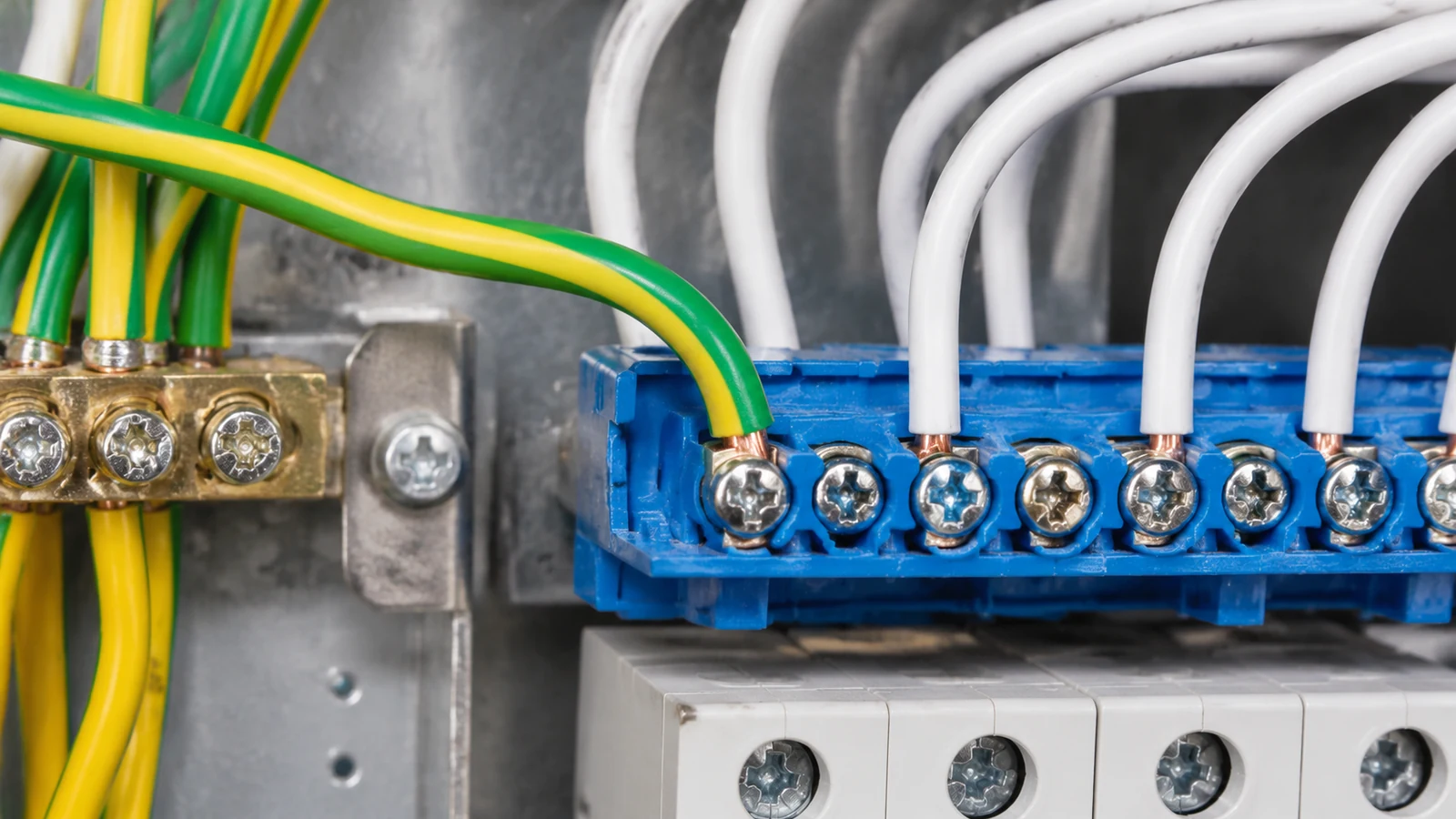
This is one of those questions where the answer sounds obvious once you know it and is genuinely dangerous to guess at. If you are searching for “can you put a ground wire on a neutral bar”, the short answer is no, and the reason is not preference. Every year panels are found with earth and neutral conductors piled onto the same bar, usually because the electrician ran out of space, or because the panel came with a single bar and a separate earth bar was never fitted. The panel still works. The lights still come on. The circuits still test fine. And the installation has quietly lost the property that makes it safe.
What goes wrong is not immediate and it is not always obvious. Putting a protective conductor onto a neutral bar creates a second path for neutral current to flow, and the consequences depend on how the panel is wired upstream. That is exactly why this needs an answer based on the wiring rules rather than on convenience.
This guide covers what the rules actually say, why the two bars have to stay apart, how to identify which is which in the field, and what to do if you find them connected. If you are selecting hardware, our guide to neutral bar types covers the physical formats, and neutral bar versus ground bar covers the difference in construction. This article is about the wiring decision, which is a different question from either.
Understanding why a ground wire on neutral bar is not permitted matters more than the rule itself, because the reason explains why the installation still appears to work.
What the wiring codes actually require
Two rule sets govern this, and which one applies depends on where the installation is. Both arrive at the same practical conclusion, which is useful, because the reasoning differs slightly between them.
Under the NEC
In the United States, the National Electrical Code requires that the equipment grounding conductors and the grounded (neutral) conductors be kept apart in the panel. Section 250.24(A)(5) requires that all equipment grounding conductors be terminated so as to be electrically separated from the grounded conductors, and where a separate bar is used for them, it must be bonded to the enclosure. Section 250.64(A) lists the points where a grounding electrode conductor may be connected, and a terminal bar in a downstream panel is not among them: the permission in 250.64(C)(2) to join sections of a grounding electrode conductor refers to busbar, not to a terminal bar in a panelboard.
The practical result in the NEC is that equipment grounding conductors belong on a grounding bar, grounded conductors belong on a neutral bar, and the two bars are bonded to the enclosure and to each other through the bonding jumper and the service-side bonding path, not by piling conductors together.
Under IEC 60364-5-54
In Europe and most countries that follow IEC practice, the requirement comes from IEC 60364-5-54, clause 543.4.3. It states that once the neutral and protective functions are provided by separate conductors, the neutral conductor must not be connected to any other earthed part of the installation. Separate terminals or bars may be provided for the protective and neutral conductors, and the PEN conductor must be connected to the bar intended for the protective conductor.
That last clause is the one that catches people out. Where a combined PEN conductor arrives at the panel, it goes to the earth bar, and the neutral is taken off separately downstream. If your panel has a single combined bar marked as a neutral bar and you arrive with a PEN, that is the wrong bar.
British practice under BS 7671 follows the same logic through its TN-C-S arrangements, where the PEN is split at the service head or metering point and the earth terminal is bonded at that point. The familiar instruction not to link the neutral and earth bars together after the split point is this same rule expressed in a different vocabulary.
Why the separation matters
It helps to think about what each conductor does. The neutral conductor carries the return current of the load in normal operation. The protective conductor carries current only when there is a fault, and it exists to make the overcurrent device operate quickly.
When you connect a protective earth conductor onto a neutral bar, you are not simply adding one more wire. You are creating a path along which neutral current can bypass the neutral conductor, and in a TN-C-S or PEN arrangement that path can run back through the supply earth, which in a metal panel means back through the enclosure and equipment metalwork.
The consequences depend on the arrangement, and they range from nuisance to dangerous:
Neutral current on exposed metalwork. In a TN-C-S arrangement with a neutral and earth bar connected together, neutral return current can flow through the panel enclosure and equipment earth paths. Metal parts that should be at zero volts develop a measurable voltage, and in a wet area that voltage is a shock hazard.
RCD and RCBO nuisance tripping or failure to trip. The residual current device measures the difference between live and return current. When part of the return current has been diverted through the earth path, the balance is disturbed and the device either trips when it should not, or fails to trip when it should.
Loss of the fault path. This is the serious one. If the protective conductor is relying on the neutral bar for its connection back to the source, then a fault to earth has to travel through the neutral bar, through the neutral conductor, and back through the supply neutral. That path is not designed for fault current, it may be a higher-resistance route than intended, and the overcurrent device may not disconnect within the required time.
The third point is the reason the rule is not negotiable. The protective conductor is the last line of defence between a person touching a metal enclosure and a lethal voltage, and it works by being a deliberately low-impedance path that a protective device can act on quickly. Sharing that path with the neutral defeats the design.
The exceptions: when a ground wire may share a bar
There are situations where an earth conductor and a neutral connection meet on the same bar, and it is worth being precise about them because they are commonly misremembered as permission to do what is asked here.
Situation
Permitted?
What the rule requires
Protective earth conductor landed on the neutral bar
No
Use a separate grounding bar bonded to the enclosure
Neutral conductor landed on the grounding bar
No
Use the neutral bar; the grounding bar is for protective conductors
Equipment grounding conductor landed on the grounding bar
Yes
The bar is bonded to the enclosure, providing the fault path
PEN conductor arriving at the panel
Yes, on the earth bar
IEC 60364-5-54 543.4.3: PEN connects to the bar intended for protective conductors; neutral splits off separately
Grounding electrode conductor in the service panel
Only at the listed connection points
NEC 250.64(A) and 250.24(A)(1); a terminal bar is not an approved connection point for extension
Grounded neutral bar in a subpanel fed by a feeder
Yes, with a bonding jumper
The bar is bonded to the enclosure with a wire-type or screw bonding jumper, keeping it distinct from the equipment grounding bar
Note the pattern. Where the codes do permit an earth-related conductor and a neutral-related connection to share a bar, it is either at the single defined bonding point at the source, or it is a bar that is explicitly a grounded neutral bar with its own bonding jumper. In neither case is it a general permission to land a protective conductor on a neutral bar.
A quick rule for checking any panel before you connect a ground wire
When you open an unfamiliar panel, the fastest way to establish whether the separation has been maintained is to check the bonding rather than to trace every conductor. Work through it in this order, and if the answer to “can you put a ground wire on a neutral bar” has come up during the inspection, treat it as a finding rather than a question.
Check
Correct
Wrong
Protective conductor landed on the bar
Green or yellow/green insulation
Any earth conductor on a blue bar
Neutral landed on the bar
White or light blue insulation
Any neutral conductor on a green bar
Bar to enclosure bonding
Earth bar bonded directly; neutral bar bonded through a jumper only
Both bars bonded to the enclosure with equal impedance
Conductor count on the neutral bar
Matches the number of circuits with neutral conductors
More than the circuits, which suggests earth conductors are mixed in
Upstream feed
Separate feeder neutral and feeder earth conductors
Earth and neutral landed on one bar at the subpanel
Two of those checks carry most of the weight. The colour of the conductor insulation is the first thing to look at and it settles most cases immediately. The second is the bonding arrangement: if both bars are solidly bonded to the enclosure with no jumper on the neutral bar, there is a path for neutral current into the panel metalwork, and that alone warrants opening up the arrangement.
Identifying the neutral bar and the grounding bar in the field
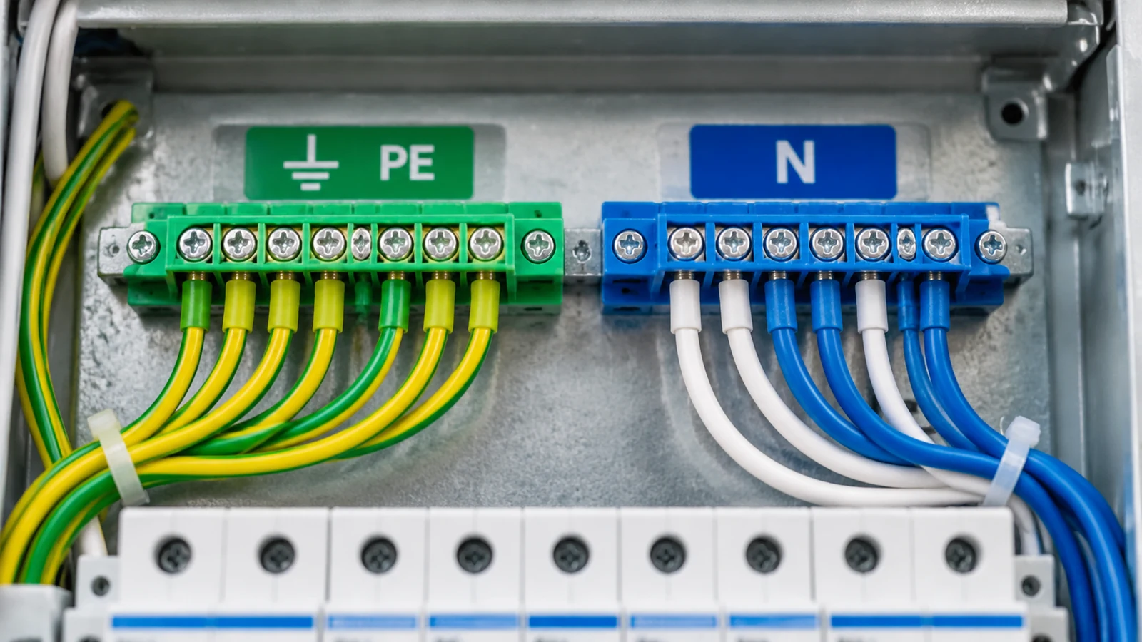
You should not have to guess, because the identification is built into the hardware. Look at the colour first, then confirm with the markings.
Feature
Grounding / earth bar
Neutral bar
Plastic colour
Green
Blue
Marking
PE, earth symbol, or “GND”
N, or a blue marker
Conductor colour
Green/yellow
White or light blue
Typical position
Bonded to the enclosure
Isolated from the enclosure, or bonded through a dedicated jumper
What lands on it
Equipment grounding conductors
Neutral conductors
The colour convention is not cosmetic. It is the fastest check available to anyone who opens the panel later, including the electrician who was not there when it was built, and it is why the terminals on our grounding and neutral bar families are moulded in green and blue respectively.
Two field checks are worth knowing. If you can remove a terminal and lift the conductor, an earth conductor is identifiable by the green and yellow insulation and by the fact that its lug is bonded to the enclosure through the bar. And if the panel has a bar that is marked or coloured as neutral, treat any conductor landing on it that is not a neutral as a fault until proven otherwise, regardless of what the paperwork says.
What to do when you find them joined
If you open a panel and find earth and neutral conductors sharing a bar, the correction is straightforward in principle: install a proper grounding bar, move the protective conductors onto it, bond it to the enclosure, and leave the neutrals where they are. In practice, a few things need checking first.
Establish whether the panel is the bonding point. If this is the service panel, or the panel containing the service disconnect, the neutral and earth connection point may already be correct and what you are seeing is a legitimate arrangement. If it is a subpanel, it is almost certainly an error.
Check for a bonding jumper. A subpanel with a grounded neutral bar requires a wire-type bonding jumper or a bonding screw through the bar to the enclosure. If the bar is isolated and has no bonding jumper, the neutral is floating and the whole panel needs correcting, not just the bar.
Test before you energise. With the supply disconnected, confirm continuity between the neutral bar and the enclosure, and confirm that the earth bar is bonded to the enclosure. Then verify the RCD or RCBO trip times after the work. This work should be done by a qualified electrician under the rules that apply in your jurisdiction, and the panel should not be returned to service until the separation has been verified.
And if the bar is full rather than the wiring being wrong, that is a design issue rather than an installation fault, and the fix is to specify the right hardware from the start: a panel with separate green and blue bars for the way count you actually have, rather than one bar and an improvised second one.
Choosing bars that make the right thing easy
The reason mistakes like this keep happening is that a neutral bar and a grounding bar are often mechanically interchangeable. The same brass bar, the same screw size, the same way pitch. Nothing about the hardware prevents the error.
What prevents it is colour, and it is worth specifying bars whose insulating housing is coloured for their function rather than left neutral. Our grounding bar families are moulded in green and the neutral bar families in blue, so the two are distinguishable from across a panel, and the colour carries through to the fixing part, the bracket and the cover.
Our A04E earth bar is a brass bar on a green ABS fixing part, with the green housing carrying the earth identification right through the assembly. The A14E grounding bar adds a full plastic cover over the whole bar, which gives finger-safe protection on live parts in the same way a shrouded neutral bar does, while keeping the earth function visually distinct. For a screw-terminal grounding bar with a shrouded moulding, the A27E grounding bar covers six to thirty ways with a PA housing rated UL94V-2 and an operating range from −30 °C to 110 °C.
All of these products are manufactured to the same 250 to 450 V voltage range and the same brass conductor with galvanised steel screws, and all can be supplied in lengths and way counts to suit the panel. If you need a specific way count, hole pattern or colour, that is a normal custom request rather than a special order.
Frequently asked questions
Can I connect a ground wire to a neutral bar in a residential panel?
No. The neutral bar is for grounded (neutral) conductors. A protective or equipment grounding conductor belongs on a grounding bar, which must be bonded to the panel enclosure. This applies whether or not the panel is a service panel or a subpanel, and it applies regardless of how many wires you need to fit.
Is it ever allowed to land an earth conductor on the neutral bar?
Only at the defined bonding point. Where a PEN conductor arrives at the panel under IEC practice, it terminates on the bar intended for protective conductors, and the neutral conductor is taken off separately downstream of that point. What is permitted is the PEN on the earth bar; it is never the earth conductor on the neutral bar. The same distinction appears in the NEC as the requirement for equipment grounding conductors to be kept electrically separate from grounded conductors.
What happens if I do connect them together?
It depends on the arrangement and on the size of the panel, which is why it should be corrected rather than assessed informally. The likely outcomes are neutral current appearing on metalwork, RCD nuisance tripping or failure to trip, and a degraded fault path that may not cause the protective device to disconnect quickly enough in a real earth fault. In a TN-C-S arrangement the consequences are most severe, because the return path runs through the supply earth and the panel metalwork.
Can I use a grounding bar where a neutral bar is called for?
No, not as a substitute. A grounding bar is bonded to the enclosure and carries protective conductors; a neutral bar is isolated from the enclosure, or bonded to it only through a dedicated bonding jumper, and carries neutral conductors. Swapping one for the other changes the fault path and the bonding arrangement of the whole panel. The two are related parts of a design, and they need to be specified as a pair.
Does the colour of the bar matter legally?
Colour is not usually the legal requirement; the requirement is that the two functions be kept separate and that identification is unambiguous. In practice, colour is the most reliable identification method available, because it survives being seen at a glance by someone who has never opened that panel before. Green for earth and blue for neutral is the convention across IEC practice, and it is why our grounding bar housings are green and the neutral bar housings are blue.
What about the neutral bar and earth bar in a subpanel?
In a subpanel fed by a separate feeder, the neutral and the equipment grounding conductors must still be on separate bars. The neutral bar in a subpanel is a grounded neutral bar: it is bonded to the subpanel enclosure with a wire-type bonding jumper or a green bonding screw through the bar, and the equipment grounding bar is separately bonded to the enclosure. What you must not do is land the feeder neutral and the equipment grounding conductors on the same bar, which is a common enough shortcut in subpanel work.
Summary
A protective earth conductor goes on the grounding bar. A neutral conductor goes on the neutral bar. They stay apart downstream of the point where the installation joins them, which under NEC practice is the service bonding point and under IEC practice is the PEN splitting point. Where a PEN conductor arrives, it lands on the earth bar, and the neutral splits off separately.
The reason this matters is not tidiness. It is that the separation is what guarantees that a fault to earth has a fast, low-impedance path back to the source, and that the protective device acts on it. Remove the separation and you have degraded the one part of the installation designed to protect people.
For panel construction, specify a green grounding bar and a blue neutral bar with the way counts the layout actually needs, so that neither bar is a compromise. Our neutral and grounding bar range covers brass and pure copper conductors, screw terminal and bridge type, DIN rail and screw fixing, from four ways to fifty. If you are working from a panel schedule and need sizes matched to it, send us the schedule and we will quote the parts against it.
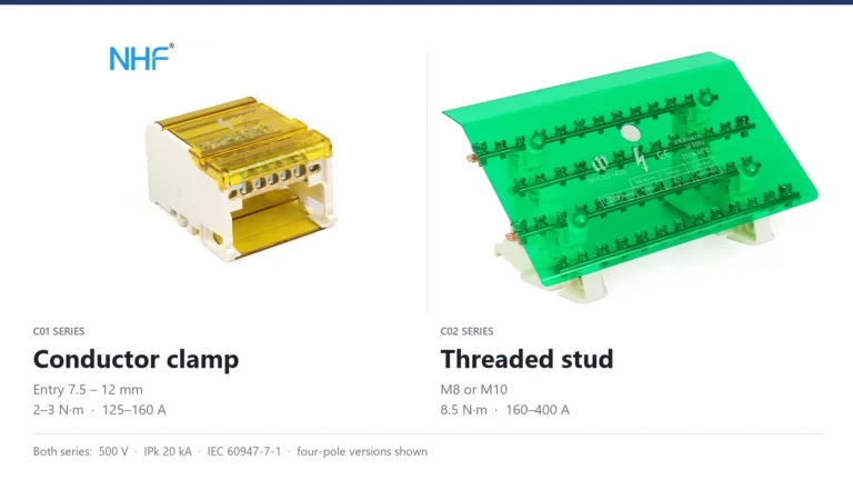
Both ranges are rated 500 V and IPk 20 kA, so the data sheet cannot choose for you. The difference sits at the input terminal: a conductor clamp with a published conductor range, or a stud that holds a cable lug.
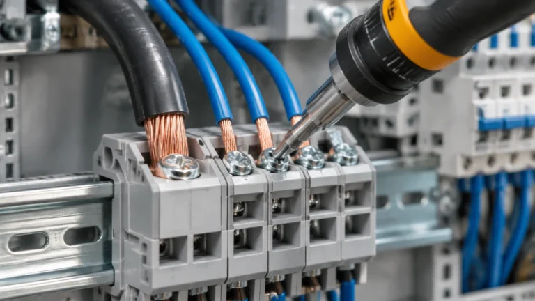
Four rules decide whether a terminal block joint runs cool or overheats: the strip length the block specifies, the separate input and output torque values, one rated conductor per clamp, and the conductor range for the ferruled size.
How to test earth continuity on a grounding bar: the dead test method, instrument and test current selection, acceptance values in ohms, and the parallel-path mistake that invalidates results.