Types of Neutral Bar: Screw Terminal, Bridge, DIN Rail and Double Row Compared
Published: Author: Rachel
Electrically, every neutral bar does one job: collect all the grounded conductors in a panelboard onto a single bus that returns current to the source. Physically, they arrive in at least six recognisable constructions, and choosing between them has far more to do with your enclosure, your assembly process and your inspection regime than with anything electrical. Pick the right family and the rest of the specification is easy. Pick the wrong one and you will fight it on every panel you build.
This guide classifies neutral bars along the four axes that actually vary — terminal structure, mounting method, row arrangement and enclosure — and then by conductor material. Use it alongside Neutral Bar Size Chart for dimensions and What Is a Neutral Bar? for the circuit fundamentals.
Axis 1: Terminal Structure
How the screw clamps the conductor determines what wire you can land, how much torque it needs, and how tolerant the assembly is of being re-terminated.
Screw terminal (direct pressure)
The screw bears directly on the conductor pressed against the bar body, either through a tapped hole in the bar or with the conductor captured under the screw head. It is the simplest construction, has the fewest parts to lose, and is the standard for branch-circuit neutrals in the 14–4 AWG range.
The limitation is that it is unforgiving of mismatch. A conductor substantially smaller than the terminal was dimensioned for will sit loosely no matter how much torque is applied, and the strand damage from over-torquing a small conductor in a large terminal is a persistent source of intermittent connections. Match the conductor to the listed range.
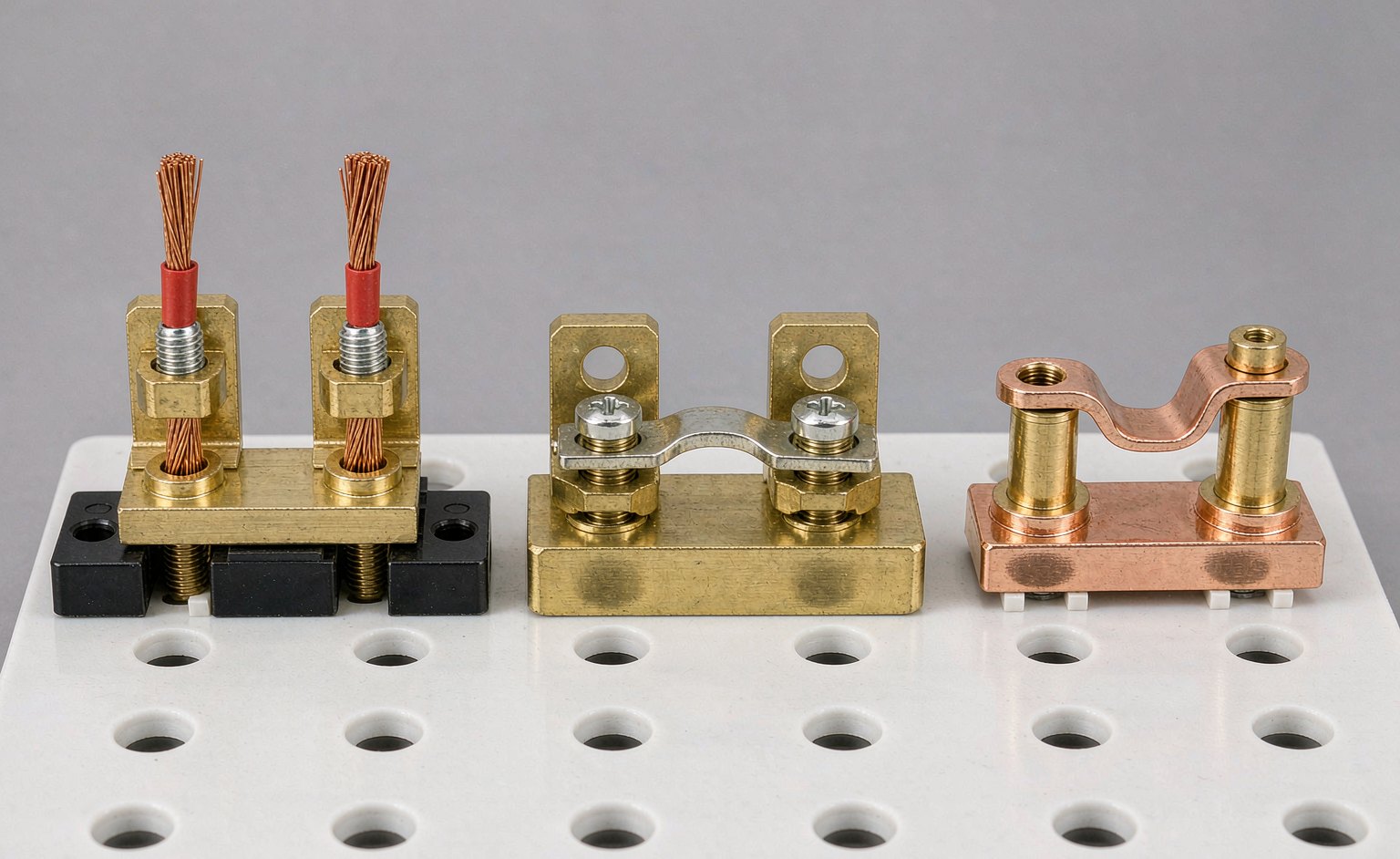
The NHA26 screw terminal neutral bar with cover is typical of the modern version: brass conductor body, galvanized iron screws, polycarbonate housing rated −40 °C to 85 °C. The NHA21 with white bracket uses the same principle where the bar needs to sit off the backplane.
Bridge type
Instead of threading directly into the bar body, each position uses a bridge clamp — a saddle that straddles the bar and is drawn down by one or two screws, gripping the conductor from above. Because the clamp distributes pressure over a wider area, bridge-type bars are more tolerant of larger and finer-stranded conductors, and they survive re-termination better since the wear surface is the replaceable bridge rather than the bar itself.
They are physically bulkier and cost more per position, which is why you find them on heavier work rather than on every residential bar. The D02 bridge type series spans 3 to 15 ways across 1.5×15, 2×20 and 3×25 cross-sections, and the D05 puts bridge terminals into a double-row body for high-density applications.
Link / U-link type
A U-shaped copper or brass link bridges between two terminals, letting you common several positions together or extend a bus across a gap without pulling a new conductor. These are a niche item — mostly used for panel modifications, phase-sequence changes and retrofit work where adding conductors is impractical — but they are worth knowing about because reaching for a “spare jumper wire” instead is usually a listing violation. Links designed for the bar are part of the assembly; a cut piece of wire is not.
The NHA02, NHA03, NHA11 and NHA15 families cover link-type construction in both brass and screw-terminal variants.
Axis 2: How It Mounts
This is the decision that most often gets made backwards — people choose the terminal count first and discover the mounting method does not suit their panel.
Mounting method
Typical construction
Best for
Watch out for
Direct panel mount on standoffs
Bar drilled with clearance holes, lifted on insulating feet
North American load centers, subpanels needing a listed isolated neutral
Mounting centre distance must match existing holes
Mount with integral insulator
Bar bonded to a moulded insulating base, single assembly
Isolation that cannot be assembled wrong in the field
Insulator height eats vertical clearance
35 mm DIN rail clip-on
Housing clips to TS35 top-hat rail
IEC distribution boards, OEM assemblies, avoided drilling
Rail deflection under heavy conductor bundles
Bracket / holder mount
Bar retained in a coloured moulded bracket
Visual function coding, low-profile retrofit
Lower current class than bolted equivalents
Screw-fastened direct mount is what the metric families are built around. The D01 series gives its mounting centres explicitly as dimension L2, which is the number to check before ordering — not the overall length.
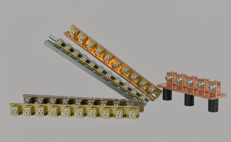
Where drill-hole patterns are unpredictable or the panel is an IEC-style board, DIN rail wins outright. Every variant in the NHA06/A06 family uses the same 35 mm mounting pitch, so you can move between 7 and 18 ways without modifying the rail or re-drilling. The NHA06 DIN rail neutral bar is rated 100 A maximum with an M4 terminal screw and a 5.3 mm conductor hole; NHA08 adds a full plastic cover to the same mounting concept.
Axis 3: Single Row, Double Row
Row arrangement is a density question, and it is usually dictated by geometry rather than by preference.
A single-row bar presents every terminal screw facing the same direction along one face. Conductors leave cleanly to one side, terminations are easy to inspect and to torque with a straight screwdriver, and there is generous room between positions. The cost is length: each way adds roughly 14 to 18 mm at a 2×20 cross-section, so a 15-way bar runs about 247 mm end to end.
A double-row bar stacks two rows of terminals in the same footprint, roughly halving the length for a given number of ways and giving much better access when space is tight. The trade-off is real: the two rows share a common body, so heat from one row adds to the other, inspection of the inner row is harder, and routing conductors out without crossing them requires more forethought. It also puts more terminals in a smaller area, which means more opportunities to land a conductor in the wrong position.
Double-row construction appears where panel space is genuinely constrained — the D03 series steps in even way-counts from 9 to 31 on a 2.5×25 body, and the D08 takes the same approach into higher cross-sections with an integrated insulator. Check the derating notes on any double-row bar: some manufacturers rate them below the equivalent single-row cross-section precisely because of the shared body.
Axis 4: Bare, Bracketed or Covered
How much insulation the assembly carries is about where it lives and who might touch it.
Bare bar. Just the conductor body and its standoffs. Appropriate inside a dead-front panelboard where access is restricted to qualified persons, and often what inspectors expect to see so they can visually verify every termination.
Bracket / holder. The bar sits in a moulded carrier — frequently colour-coded blue, green, white, black or yellow. Used for identification, light mechanical protection and keeping the bar off the backplane without separate standoffs. Examples include the NHA12 and the L-shaped NHA04 with blue fixing part .
Full plastic cover. A complete enclosure around the bus, usually polycarbonate or nylon, leaving only the screw access openings. Needed where the assembly must be touch-safe or finger-safe in service, or where an enclosure design leaves the bar within reach of a door opening. The NHA26 uses UL94 flame-retardant PC rated to 85 °C; the NHA11 uses UL94V-2 nylon 66 rated to 110 °C.
Integral insulator. Heavier assemblies where the insulating base is structural — see the D07 pure copper bar with insulator , whose 110 mm body width is mostly insulator rather than conductor.
Temperature rating is the specification people miss when moving from a bare bar to a covered one. The cover material sets the upper limit: polypropylene housings typically land in the −40 °C to 65 °C band, polycarbonate reaches 85 °C, and nylon 66 goes higher still. A covered bar in a hot enclosure carries the rating of its housing, not of its brass.
Axis 5: Conductor Material
Three materials dominate, and the differences are more practical than they first appear.
Material
Resistivity behaviour
Mechanical
Where it fits
Brass, often nickel-plated
Higher resistivity than pure copper
Hard-wearing threads, resists stripping over repeated re-termination
Branch-circuit neutrals, general panel building
Pure copper
Lowest resistivity of the three
Softer; threads wear faster under repeated torque cycles
High-current bars, specifications calling out copper explicitly
Brass-plated copper
Copper core performance, brass contact surface
Good compromise on both counts
Where the specification wants copper conductivity and durable threads
Also check the conductor-material marking on the bar itself. A bar marked AL9CU is listed for aluminium conductors; one marked CU alone is not. Terminating aluminium on a copper-only bar without the right compound and hardware is one of those mistakes that fails slowly, over years, and is expensive to find afterwards.
The D06 pure copper neutral bar and the D07/D08 variants cover the copper end of this range, while brass with a nickel-plated surface remains the default across the D01 and D02 families.
Matching the Family to How You Build
The same electrical requirement resolves to different answers depending on who is assembling the panel and how often.
A volume panel builder repeating a known design wants repeatability above all: a fixed bar part number, a fixed mounting pitch, and — ideally — DIN rail so nothing has to be measured twice on the line. Consistency beats flexibility here, and it is why rail-mounted families exist at all.
A field retrofit in an occupied building has almost the opposite constraints. Existing hole patterns are whatever they are, the enclosure cannot usually be modified, and whatever was installed decades ago may not match anything current. Direct-mount families that publish their mounting centre dimension and offer custom lengths, widths, hole diameters and way-counts are what make these jobs finishable — forcing a standard part into non-standard holes is how you end up with a bar that cannot be torqued flat.
An OEM equipment builder exporting into multiple markets tends to need the most configurable combination: IEC construction with DIN rail mounting for European panels, North American dimensions for UL work, and a covered version where the end product must be touch-safe. Choosing one supplier whose families share a numbering logic across all three makes certification and documentation far less painful than mixing four catalogues.
Specification Mistakes Worth Avoiding
Specifying the cross-section instead of the part. Two manufacturers’ 3×25 bars are not interchangeable. Beyond cross-section, the rated ampacity depends on the terminal hardware, the standard it was tested to and the permitted temperature rise — which for covered bars means the housing material, not the metal. Specify the exact model.
Ignoring the housing temperature rating. Moving from a bare bar to a covered one in a hot enclosure silently lowers the assembly’s ceiling. Polypropylene typically caps around 65 °C, polycarbonate reaches 85 °C, nylon 66 goes higher. Check it against your enclosure’s internal temperature, not the ambient outside it.
Assuming rows are electrically interchangeable. On a double-row bar the inner row runs warmer and is harder to inspect. Manufacturers sometimes publish different ratings or derating notes per row, and ignoring that is how a compliant-looking installation ends up operating above its tested temperature rise.
Mixing neutral and equipment grounding conductors to fill empty positions. It is convenient and it is wrong. Each conductor has its designated bar, and doubling up defeats the separation that makes the whole bonding arrangement work. If you have run out of positions, add a bar — the count and the cost are both smaller than the correction.
Choosing: A Working Sequence
Start with the enclosure, not the bar. Is there a DIN rail and no drill pattern? DIN rail mounted. North American load center with existing standoffs? Direct mount.
Check whether touch-safety is required. If unqualified people can reach it, or the standard for your market requires finger-safety, cover or full-insulator construction is mandatory rather than optional.
Count ways with 25% spare , then check whether the resulting single-row length fits. If not, move to double row rather than dropping your spare margin.
Match terminal screws to your actual conductor range. Mostly 14–10 AWG? Direct screw terminal. Large, fine-stranded or frequently re-landed? Bridge type.
Pick material last , unless the specification dictates it — brass default, copper where conductivity or a written spec demands it.
Whatever you land on, remember there are two bars in most panels doing different jobs. If you are specifying the bonded side at the same time, the mechanical steps for that one are covered in How to Install a Ground Bar, and the functional split between them in Neutral Bar vs Ground Bar.
Frequently Asked Questions
Can I use any terminal block as a neutral bar?
No. A neutral bar in a panelboard has to be part of the listed assembly — or a listed field-installable kit specifically identified for that panel. Substituting a generic terminal block ignores fault-current withstand, which is not what a distribution terminal is tested for. This comes up in exactly the situations described in What Is a Busbar?: the component looks interchangeable and its test regime is nothing like equivalent.
Is a covered bar always safer?
For touch protection, yes. But covers hide the termination from visual inspection, restrict cooling, and cap the temperature rating at whatever the plastic will stand. Inside a dead-front panelboard accessed only by qualified persons, a visible bare bar often serves the installation better.
Why does the same length housing over here carry a different current rating than the one over there?
Because the rating is set by the assembly, not by one dimension. Conductor cross-section, terminal screw size, the number of rows sharing a body, housing material and temperature rise limit all interact. Never infer a rating from a cross-section or a photograph — take it from the manufacturer’s published figure for that exact model.
Do double-row bars need derating?
Frequently, and the manufacturer’s datasheet is the only authority on it. Two rows sharing one conductive body put heat into the same mass, and some manufacturers publish a lower rating for the double-row version of a cross-section than for its single-row equivalent.
What is the difference between a neutral bar and a neutral link?
The terminology varies by market. In IEC practice “neutral link” often refers to a smaller disconnectable link — the component you open to isolate the neutral for testing or maintenance. In panel-builder usage it frequently just means a neutral bar. Check whether the part has a disconnecting function before substituting one for the other.
Closing Note
None of these constructions changes what the component does electrically. What they change is whether your next fifty panels go together quickly, pass inspection without discussion, and can still be modified five years from now. Mounting method first, touch-safety requirement second, then row count, terminal structure and material — in that order, most wrong answers eliminate themselves before you reach a catalogue.
Four constraints determine neutral bar size: terminations needed, unbalanced current per NEC 220.61, largest conductor and mounting centres — with real dimension charts.
The neutral bar is the return path for every line-to-neutral load. How it works, where it sits, when it must be isolated from the enclosure, and the rules that govern it.
A practical guide to installing a ground bar in a main panel or subpanel: selection, bonding to the cabinet, one conductor per terminal, torque to spec and continuity checks.