What Is a Neutral Bar in an Electrical Panel? Purpose, Position and Wiring
Published: Author: Rachel
Open almost any distribution panel and the neutral bar is the strip of metal that every white wire in the cabinet eventually finds. It is easy to mistake it for a passive parking place for conductors — a tidy collection point and nothing more. In reality it is the return half of every 120 V circuit in the building, and the single most common source of the mysterious “half the house goes dim, the other half gets bright” complaints that electricians are called out to diagnose. Understanding what the neutral bar does, where it sits and what it must not be bonded to is the difference between a panel that behaves predictably and one that quietly energizes its own enclosure.
This guide covers the neutral bar specifically: its function as a grounded conductor termination point, its physical position inside service equipment and subpanels, how it differs from the ground bar that sits beside it, and the wiring rules that govern what can go in it. If you need the sizing arithmetic, see Neutral Bar Size Chart; for the physical formats the same component comes in, see Types of Neutral Bar.
The Neutral Bar, Defined Without Ambiguity
A neutral bar is a listed terminal assembly — one conductive body, usually brass or copper, drilled and tapped to accept a row of screws — that provides a common termination point for all grounded conductors (neutrals) in a panelboard. Current leaving the transformer on a phase conductor, passing through a load, comes back to the transformer through this bar and the service neutral conductor connected to it. It carries current continuously whenever any line-to-neutral load is running.
The terminology matters because it drives the code language. In NEC usage the neutral is the grounded conductor: a conductor that is intentionally connected to ground, but only at one defined point. It is not the grounding conductor. Those are different animals with different jobs, and the fact that both terminate in the same panel is the source of nearly all field confusion on this topic.
Term
NEC name
Carries current
Connected to earth
Neutral conductor
Grounded conductor
Yes, continuously under load
At one point only
Equipment ground
Equipment grounding conductor (EGC)
No, except during a fault
Yes, throughout
Neutral bar
Grounded conductor terminal bar
Yes
Only in service equipment
Ground bar
Equipment grounding terminal bar
During fault only
Yes
Note the asymmetry in that table. The neutral bar carries current all day and is bonded to earth at exactly one location. The ground bar carries current essentially never and is bonded everywhere. Wiring the two as though they were interchangeable produces a system where normal return current flows on the enclosure, on conduit, on equipment frames — every bonded metal surface in the building.
Why the Panel Even Needs One
In a 120/240 V single-phase system, the transformer secondary has three terminals: two line ends and a center tap. The center tap is the neutral. Because it sits at the electrical midpoint, phase-to-neutral reads 120 V and phase-to-phase reads 240 V. Any 120 V load — every receptacle, most lighting, all electronics — is connected between one phase and that center tap.
All of those individual branch-circuit neutrals have to get back to the center tap somehow. Running each one separately to the transformer would be absurd, so the panel collects them on one bus and runs a single larger service neutral from that bus back to the source. The neutral bar is that collection point. Every white wire landed on it is a tributary feeding into one river.
There is a useful consequence here that surprises people: the current on the service neutral is the difference between what the two phases are drawing, not the sum. If L1 feeds 12 A of lighting and L2 feeds 8 A of receptacle load, 4 A flows on the neutral. Balance the loads across the two legs and neutral current approaches zero. This is why two legs feeding a shared neutral in a multi-wire branch circuit only put the imbalance on that conductor — and it is why losing the neutral in a multi-wire circuit is catastrophic rather than merely inconvenient, because the shared conductor stops being a return path and becomes a voltage divider between two now series-connected loads.
That same cancellation principle drives the whole sizing argument in Neutral Bar Size Chart: the neutral does not automatically have to match the phase conductors, and NEC 220.61 spells out exactly how much it can be reduced.
Where the neutral physically sits
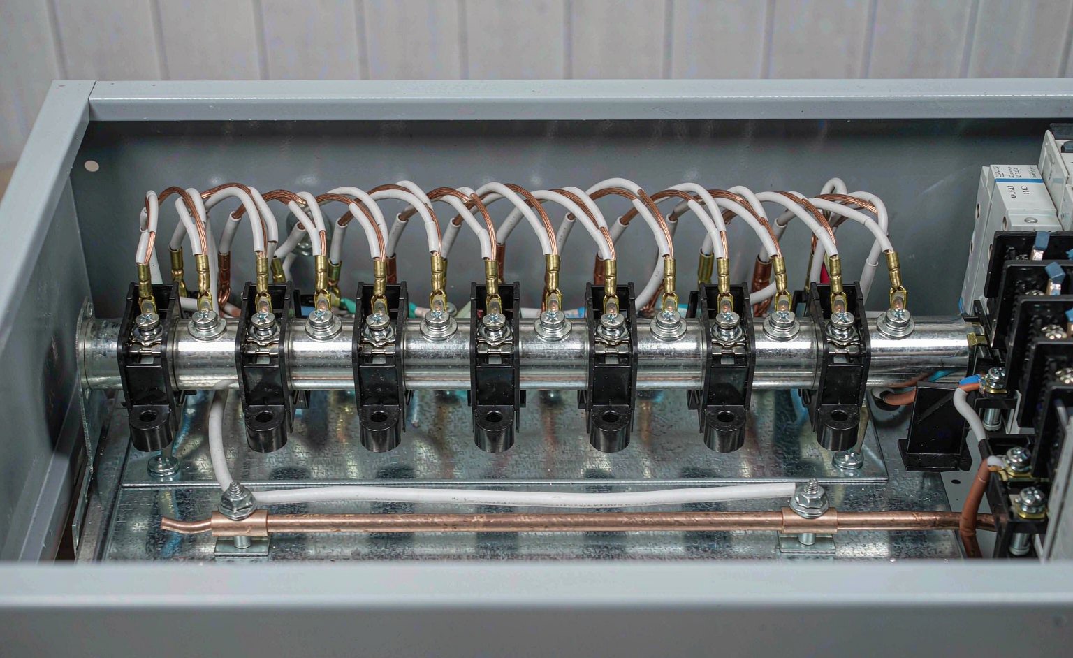
In a typical North American load center, the neutral bar runs as one or two long strips flanking the row of breakers, supported above the enclosure’s backplane on insulating standoffs. Those standoffs are doing critical work — they are what keeps the bar electrically isolated from the metal can. Flanking pairs are common in larger panels and connected by a strap so both halves sit at the same potential.
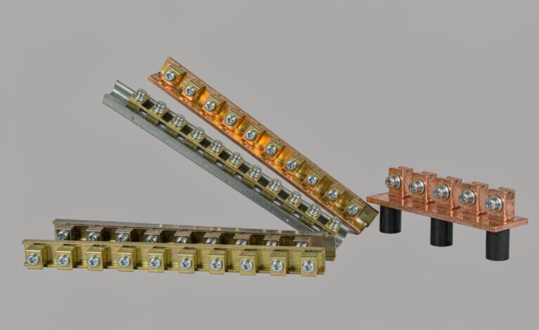
Separate, free-standing bar assemblies are used when the panel does not integrate one, or when capacity has run out. Those mount either on standoffs to the backplane or clip directly to a 35 mm DIN rail. Our NHA26 screw terminal neutral bar with cover is representative: a brass conductor body, galvanized steel screws, and a polycarbonate housing rated −40 °C to 85 °C with UL94 flame-retardance, offered standard in blue and green for visual phase or function coding.
IEC-style distribution boards and consumer units arrange things differently — the neutral often arrives as a factory-fitted insulated bar assembly rather than something you add — but the isolation principle holds. Except at the single permitted bonding point, the neutral bar must never touch the enclosure.
Service Equipment vs Subpanel: The One Rule That Decides Everything
Whether a neutral bar is bonded to its enclosure is not a preference, a regional habit, or a judgment call. It is determined entirely by where that panel sits relative to the service disconnect, and getting it wrong is one of the few panel mistakes that creates a shock hazard with no visible symptom.
Panel type
Neutral-to-enclosure
Feeder required
Why
Service equipment (main panel)
Bonded with the main bonding jumper
3-wire from the utility
NEC 250.24 requires the bond at the service disconnect — the single point where neutral meets earth
Subpanel downstream
Isolated on insulating standoffs
4-wire: two hots, isolated neutral, separate EGC
Bonding again puts a second parallel path for return current onto the grounding system
Separately derived (transformer, generator)
Treated as its own service
Per the source configuration
The bonding point moves to the new source’s disconnect
In service equipment, you can land neutrals and equipment grounds on the same bar, because that bar is bonded to the enclosure and the enclosure is grounded — the N-G connection happens once, right there. In any panel downstream of that point, the neutral bar must be isolated from the can and a separate ground bar bonded to the can takes the EGCs. Remove or leave uninstalled the green bonding screw in a convertible load center that is being used as a subpanel; install it when the same product serves as service equipment. Confirmed August 2026 against the current NEC cycle.
The distinction between the two bars is worth reading in full rather than skimming — Neutral Bar vs Ground Bar covers the comparison, and How to Install a Ground Bar walks the mechanical install for the bonded side.
Wiring Rules That Actually Get Enforced
Three rules account for the overwhelming majority of neutral bar defects found at inspection, and all three are easy to comply with if you plan for them before you start pulling conductors.
One neutral per terminal
NEC 408.41 requires each grounded conductor to terminate in an individual terminal that is not also used for another conductor. The 2023 language reinforced it, and NEC 110.14(A) backs it from the general side: terminals intended for more than one conductor must be so identified. Since panel neutral bars are almost never identified for multiple conductors, one wire per screw is the default and essentially universal rule.
The reasoning is mechanical rather than electrical. Loosening one screw to remove one neutral momentarily loosens every other neutral sharing that screw — including conductors belonging to circuits that were never de-energized. Lose a multi-wire branch circuit’s shared neutral for even a fraction of a second and you have just put 240 V across a set of 120 V loads.
Double-lugging neutral conductors was common practice before roughly 2002 and was never compliant with UL 67, which has always required an individual terminal for each branch-circuit neutral. Panels wired before the code language changed are full of them. That history is not a permission.
Neutral and ground never share a terminal
Beyond the one-conductor rule, a neutral and an EGC must not be landed together even where the bar is bonded. Doing so defeats the separation, makes the return-current path ambiguous for anyone testing later, and violates the terminal’s listing. Neutral goes to the neutral bar; EGC goes to the ground bar; they meet once, at the main bonding jumper.
Torque to the marked value
NEC 110.14(D) requires terminals to be tightened to the manufacturer’s specified torque, with a calibrated tool, where a value is marked or provided. Under-torqued neutral screws are a slow failure: a slightly loose connection heats under load, the heat accelerates oxidation, the oxide raises the resistance further, and the cycle continues until the terminal visibly discolors. Why Is My MCB Busbar Overheating? traces the same mechanism on the breaker side of the panel.
Identifying the Neutral Bar in an Unfamiliar Panel
Second-hand panels, undocumented additions and cabinets whose label has long since fallen off are routine. Four reliable tells:
Conductor color. The bar with white or grey conductors is the neutral bar. If it is green, bare copper or green-yellow, that is the ground bar.
Mounting hardware. Insulating standoffs, a molded non-conductive base, or visible plastic barriers underneath indicate a bar that is meant to be isolated — a neutral bar in anything other than service equipment.
Direct metal contact. A bar screwed straight into the backplane with no insulating element is bonded to the enclosure, which makes it a ground bar or the bonded neutral bar of service equipment.
The number and pattern of positions. Neutral bars typically carry positions matched to the breaker count, since almost every branch circuit needs one. Ground bars frequently have fewer or more depending on whether the manufacturer expects one or two EGCs per position.
Do not rely on plating color alone to tell the bars apart — neutral bars are commonly nickel-plated and silver-toned, but tin plating and bare copper appear depending on manufacturer and vintage. Combine at least two of the four signals above before concluding anything.
What Actually Goes Wrong
Bootleg grounds. In old receptacle upgrades, a three-prong outlet gets installed with a jumper from its neutral screw to its ground screw. The tester says the outlet is wired correctly. The outlet is lethal. If that neutral opens anywhere upstream, the jumper puts full line voltage on the plate screws and on every grounded chassis plugged into it. The ground path must run uninterrupted back to the panel’s ground bar, never borrowed from the neutral.
Subpanels bonded downstream. Leaving the bonding screw installed in a subpanel creates a second N-G connection. Return current divides between the intended neutral conductor and the parallel path through the grounding system and building steel. Everything metal that should be at zero volts now carries measurable current continuously.
Switched neutrals. NEC 404.2(B) prohibits switching the grounded conductor in most occupancies, because opening the neutral de-energizes the load on paper while leaving the fixture’s screw shell live. It is still found in older work and in DIY lighting retrofits.
Harmonic overloading. Single-phase electronic loads — LED drivers, switch-mode supplies, UPS input stages — draw current in non-sinusoidal pulses. Their third-harmonic components do not cancel between phases the way fundamental current does; they add arithmetically on the neutral. A neutral conductor feeding a modern office floor can genuinely carry more current than the phase conductors feeding it. NEC 220.61(C) removes any permitted reduction for exactly this reason.
Frequently Asked Questions
Is the neutral bar the same thing as the ground bar?
Only inside service equipment, and even then only in the sense that one bar can serve both functions because it is bonded there. Downstream of the service disconnect they are separate components with separate requirements, and they must never be jumpered together.
Why does the neutral bar sit on plastic standoffs?
Those standoffs electrically isolate the bar from the metal enclosure. In a subpanel, isolation is mandatory — the neutral must have exactly one connection to earth, back at the service equipment, and contact with the enclosure would create a second one. In service equipment the isolation is deliberately bridged by the main bonding jumper instead.
Can I put two neutral wires in one hole?
No, unless the terminal is specifically identified and marked for more than one conductor of that size and type. NEC 408.41 requires an individual terminal per grounded conductor, and the great majority of neutral bars carry no marking permitting anything else.
Can I add a second neutral bar if mine is full?
Yes, using a listed bar kit appropriate for the panel and following the manufacturer’s instructions for how it bonds to or is isolated from the existing assembly. Never solve a full bar by doubling up conductors — every other option is better than that one.
What material should the bar itself be?
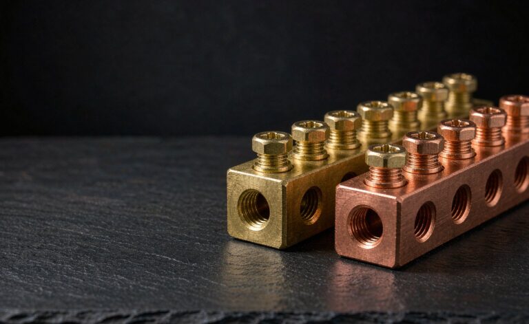
Brass and copper are both standard. Brass is harder-wearing and resists screw-thread damage over repeated re-terminations; pure copper offers lower resistivity, which matters at higher currents. Both need the correct conductor material compatibility marking — a bar marked AL9CU accepts aluminium conductors, one marked CU alone does not. The comparison is covered in more depth in Types of Neutral Bar.
The Bottom Line
The neutral bar is not a conductor parking space. It is the return path for every line-to-neutral load in the building, it carries real current continuously, and it touches earth at exactly one point in the entire system. Get those three facts right, respect the one-conductor-per-terminal rule, and keep it isolated downstream of the service disconnect — and the bar will do its job silently for the life of the installation. Everything that goes wrong with neutrals, from flickering lights to live equipment frames, traces back to one of those principles being violated.
Four constraints determine neutral bar size: terminations needed, unbalanced current per NEC 220.61, largest conductor and mounting centres — with real dimension charts.
A practical guide to installing a ground bar in a main panel or subpanel: selection, bonding to the cabinet, one conductor per terminal, torque to spec and continuity checks.