Neutral Bar Size Chart: How to Size a Neutral or Earth Bar for Your Panel
Published: Author: Rachel
Sizing a neutral bar is not one calculation. It is four constraints applied simultaneously, and whichever one you overlook is the one that fails. Count only the circuits and you may end up with a bar whose largest terminal cannot accept your feeder neutral. Size only for conductor ampacity and you may order a bar too long to fit between the panel’s knockouts, or whose mounting centres do not line up with any hole you are prepared to drill. This guide walks all four constraints in order, then puts real dimensional data on the table so you can pick a part number rather than a description.
Two working assumptions: the panel is single-phase 120/240 V or three-phase four-wire, and you are working under NFPA 70 (the NEC). Metric-dimensioned terminal bars are shown because that is how most bar assemblies are actually catalogued, including everything in our own range; the electrical sizing below converts to AWG at the point where the two systems meet.
The Four Constraints, In Order
Every neutral bar selection resolves to answering four questions. Answer them in this sequence, because a later answer will sometimes force you back to an earlier one.
#
Constraint
Question
What governs it
1
Quantity
How many neutral terminations does the panel need today, plus spare?
Circuit count + 25% spare capacity
2
Ampacity
What is the maximum unbalanced neutral current the bar must carry?
NEC 220.61, then Table 310.16
3
Conductor range
What is the largest single conductor any one position must accept?
Largest feeder or branch conductor; the main neutral lug is usually a separate part
4
Mechanical fit
Does it physically fit, and do the mounting centres work?
Overall length L1, mounting centres L2, height above the backplane
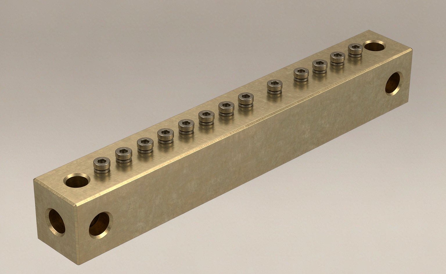
Constraint 4 is the one nobody budgets time for, and it is why bars get returned. A 15-way neutral bar in the 3×25 class is 247 mm long end to end. Measure the available mounting span in your enclosure before you order, not after.
Constraint 1: How Many Ways You Actually Need
Start from the number of branch circuits requiring a neutral — essentially every 120 V circuit in the panel — then add a minimum of 25% spare positions. Some jurisdictions and many neutral bar manufacturers’ instructions call for more.
A useful rule of thumb: if you fill a bar completely on installation day, you have specified it wrong. The next technician who opens the panel will either stack two conductors in one terminal or leave a circuit without a neutral landing at all, and both outcomes are worse than the few dollars the longer bar cost. The sizing tables below list available way-counts per family so you can move up a way-count or a cross-section rather than guess.
Multi-wire branch circuits complicate the count slightly in the other direction — two ungrounded conductors share one neutral, so they consume one position between them, not two. Do not let this tempt you below the 25% margin.
Constraint 2: Neutral Ampacity Per NEC 220.61
The neutral does not automatically have to be the same size as the phase conductors, because it only carries the imbalance. NEC 220.61 defines that imbalance as the maximum net calculated load between the neutral and any one ungrounded conductor, then permits three specific reductions.
The stepping sequence
Establish the neutral load. Include every line-to-neutral load at 100% (continuous loads already counted at 125% upstream). Exclude pure 240 V / 208 V line-to-line loads entirely — a water heater, a straight EV charger or an AC compressor contributes nothing to neutral current.
Apply 220.61(B)(1). Household electric ranges, wall ovens, counter-mounted cooking units and clothes dryers may be taken at 70% of their feeder load when computing the neutral.
Apply 220.61(B)(2). For the overall neutral load above 200 A: first 200 A at 100%, remainder at 70%.
Hold back anything non-linear. 220.61(C) permits no reduction for the portion of the load that is non-linear — LED drivers, switch-mode power supplies, UPS input stages, VFD front ends, electronic ballasts. If harmonics are significant, treat that slice at 100% and apply the reductions only to what remains.
Convert to conductor size using Table 310.16 at the column matching your lowest-rated termination, usually 75 °C.
Step 4 is where most residential and light-commercial calculations quietly go wrong. Third-harmonic currents from single-phase switch-mode loads do not cancel between phases the way fundamental current does — they add. A neutral feeding a modern office floor can legitimately carry more current than the phase conductors feeding it, which is precisely why the code withholds the reduction there.
Worked example
A detached garage subpanel fed from a 200 A main. The 120 V lighting and receptacle load calculates to 85 A total, distributed across both legs so that the maximum unbalanced load is 55 A. A well pump and an EV charger add 60 A of pure 240 V load.
Step
Calculation
Result
Neutral load contributions
120 V loads only; 240 V pump and charger contribute 0 A
55 A unbalanced
220.61(B)(2) reduction
Load is below 200 A, so no reduction applies
55 A
Phase conductors
#3 AWG Cu, 75 °C column, 100 A subpanel rating
#3 AWG
Neutral conductor
#8 AWG Cu rates 50 A — too small; #6 AWG Cu rates 65 A
#6 AWG Cu
EGC
Table 250.122 for a 100 A overcurrent device
#8 AWG Cu
So the feeder is #3/#3 hot with a #6 neutral — legal, and materially cheaper than matching all three. Two caveats. NEC 250.24(C) does not permit the grounded conductor to be smaller than the required grounding electrode conductor for a service, and many authorities having jurisdiction simply require full-size neutrals in feeders because they expect harmonic loading later. Ask before you save money on this line item.
Note that this calculation sizes the neutral conductor, not the neutral bar itself. The bar itself carries its own published current rating, which comes from the manufacturer and its listing — not from your arithmetic. Size the conductor per 220.61, then select a neutral bar whose rated ampacity equals or exceeds it.
Constraint 3: Reading a Metric Bar Parameter Table
Dimensional tables for panel-mounted neutral bars use a compact set of fields. They are consistent across most manufacturers, but rarely explained:
Field
Meaning
Why you care
Ways
Number of conductor termination positions
Constraint 1
Spec (mm)
Body cross-section — thickness × width of the conductive bar
Drives current-carrying capability; 3×25 = 75 mm²
L1 (mm)
Overall length end to end
Whether it fits the space you have
W (mm)
Overall width across the body — effectively bar height for tall sections
Clearance to the dead front and to adjacent breakers
H (mm)
Standoff / profile height above the mounting plane
Bend radius room for the conductors leaving the terminals
L2 (mm)
Mounting centre-to-centre distance
The field people forget. Determines whether existing holes work
Screw size
Terminal screw thread, e.g. M5×8 with two M8 mounting screws
Maximum conductor each position accepts; torque tooling
Two practical observations on the Screw size column. Entries written as M5*8(M8*2) mean eight M5 terminal screws plus two M8 positions, and in practice the two larger ones are usually intended for the heavy feeder or bonding conductors while the small positions take branch circuits. A double-row bar will show more terminal screws than it has ways in one direction, because positions sit in two parallel rows.
A caution worth stating plainly: do not convert the body cross-section into an amp rating yourself. A given cross-section’s rating depends on the standard it was tested to, the permitted temperature rise, installation orientation, enclosure ventilation and — frequently — the weakest link in the assembly, which is often the terminal screw rather than the bar body. Use the manufacturer’s published rating. The Types of Neutral Bar guide covers how those ratings differ between construction families.
The Charts: Real Dimensions by Family
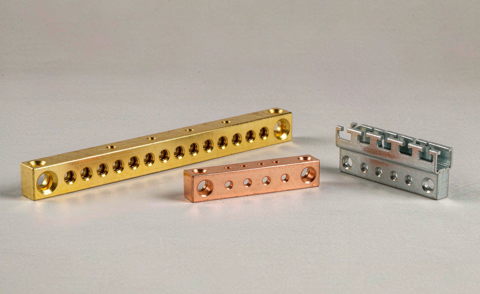
Below are actual catalogue dimensions for three representative neutral bar families. Use these charts to sanity-check neutral bar enclosure fit and to see how the way-counts step within a family.
Single-row brass / nickel-plated — D01 class
Brass with a nickel-plated surface and galvanized steel screws. The broadest range of cross-sections in one family, which makes it the usual starting point for panel builders who need several ratings from one supplier.
Model
Ways
Spec (mm)
L1 (mm)
H (mm)
W (mm)
L2 (mm)
Screw
D01/3-0215
3
1.5×15
68
2
15
58
M6×3
D01/7-0215
7
1.5×15
116
2
15
104
M5×5 (M8×2)
D01/5-0220
5
2×20
107
2
20
94
M6×3 (M8×2)
D01/10-0220
10
2×20
177
2
20
163
M6×8 (M8×2)
D01/15-0220
15
2×20
247
2
20
233
M6×13 (M8×2)
D01/7-0325
7
3×25
152
3
25
138
M8×7
D01/10-0325
10
3×25
208
3
25
—
M8×10
Note how the length grows roughly 14–18 mm per added way at 2×20 — useful for interpolating when you need a count not listed. The D01 series covers 3 to 15 ways across these three cross-sections, and lengths, widths, hole diameters and way-counts can all be customized when a standard part will not do.
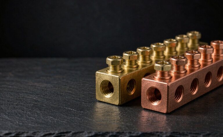
Pure copper, higher cross-section — D06 class
Pure copper body with optional brass plating and galvanized steel screws. Chosen where conductivity per unit volume matters, or where the specification calls out copper explicitly.
Model
Ways
Spec (mm)
L1 (mm)
H (mm)
W (mm)
L2 (mm)
Screw
D06/4-0325
4
3×25
117
3
25
98
M8×4
D06/6-0325
6
3×25
155
3
25
136
M8×6
D06/8-0325
8
3×25
193
3
25
174
M8×8
D06/12-0325
12
3×25
270
3
25
254
M8×12
Every position here is M8 — this family suits heavier conductors rather than branch-circuit wiring. If your branch neutrals are 14 to 10 AWG and only the occasional feeder is large, a mixed-screw family such as D01 is usually the better call. See D06 pure copper neutral bar for the full listing.
35 mm DIN rail mounted — NHA06 (A06) class
Brass conductor, galvanized iron screws, polypropylene housing rated −40 °C to 65 °C, clips to standard 35 mm top-hat rail. This is the format to reach for in IEC-style distribution boards and in OEM assemblies where drilling the backplane is not an option.
Model
Ways
Spec (mm)
L1 (mm)
W (mm)
H (mm)
L2 (mm)
Screw
Hole Ø (mm)
A06/7-0609
7
6×9
51
13
31
35
M4×7
5.3
A06/10-0609
10
6×9
71
13
31
35
M4×7
5.3
A06/12-0609
12
6×9
85
13
31
35
M4×7
5.3
A06/15-0609
15
6×9
106
13
31
35
M4×7
5.3
A06/18-0609
18
6×9
126
13
31
35
M4×7
5.3
L2 stays at 35 mm across the whole family — that is the DIN rail pitch doing its job, so you can swap way-counts without touching the rail. Full details on the NHA06 DIN rail neutral bar product page.
Constraint 4: Fit, Mounting Centres and Orientation
Before committing to a part:
Measure L2 against reality. The mounting centre distance must match existing standoffs or the span you can drill. Adapting with slotted holes usually means the bar cannot be torqued flat, and a bar that rocks under torque will loosen in service.
Check conductor bend radius. The tallest conductor leaving the bar plus its bend radius has to clear the dead front and any adjacent gutter. A 25 mm tall body carrying 35 mm² conductors needs far more room than the drawing suggests.
Confirm isolation hardware. In a subpanel the bar must ship with insulating standoffs or a non-conductive base. A bar and its insulation together must be rated for the panel’s voltage, available fault current and conductor material.
Verify way numbering against rows. Double-row assemblies pack far more positions into the same length, which is why the D03/D04 and D08 families exist — useful when the panel is wide but not long.
Frequently Asked Questions
Can the neutral bar be smaller than the phase conductors?
Often yes, where NEC 220.61 permits it and your AHJ accepts it — the neutral only carries the imbalance. But 220.61(C) removes that allowance wherever non-linear loads make up a significant share, service grounded conductors still cannot drop below the GEC size required by 250.24(C), and many jurisdictions simply require full-size neutrals regardless. Confirm with your inspector before you order wire.
How much spare capacity should I leave?
A minimum of 25% unused positions. It is the first thing an inspector flags on a panel addition and it is far cheaper than a call-out later to retrofit a longer bar into a populated cabinet.
How many perforations do I count per terminal
One position per branch-circuit neutral, in line with NEC 408.41’s individual-terminal requirement. Multi-wire branch circuits share one neutral between two ungrounded conductors, so they take one position between them — though this does not justify dropping below your spare margin.
Is a bigger cross-section always better?
Not necessarily. A heavier neutral bar costs more, occupies more space, and sometimes has larger minimum screw sizes that will not clamp small branch conductors properly. Match the bar to the largest conductor and the actual load, then take one step above — not three.
Do I size the earth/ground bar the same way?
The mechanical steps are identical — count terminations, check the largest EGC, measure L2 — but the electrical sizing comes from Table 250.122 for equipment grounding conductors and Table 250.66 for grounding electrode conductors, not from 220.61. The ground bar carries fault current rather than continuous load, so the calculation is driven by the overcurrent device rating and the electrode conductor size instead. Terminal-of-choice for many adding that bar to an existing panel is the approach in How to Install a Ground Bar.
Putting It Together
Walk the four constraints once, in order: count what you need plus a quarter more, compute the maximum unbalanced neutral current under 220.61 and convert it to a conductor size, confirm the largest conductor any single position must accept, then check that L1 fits your space and L2 matches your holes. Each answer constrains the next, and together they reduce the catalogue to a handful of candidates.
If you are still deciding between construction families rather than between part numbers — screw terminal versus bridge type, single versus double row, panel mount versus DIN rail — that comparison lives in Types of Neutral Bar. And for first principles on what the component does in the circuit, start with What Is a Neutral Bar?
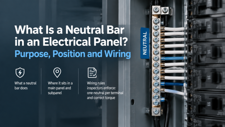
The neutral bar is the return path for every line-to-neutral load. How it works, where it sits, when it must be isolated from the enclosure, and the rules that govern it.
A practical guide to installing a ground bar in a main panel or subpanel: selection, bonding to the cabinet, one conductor per terminal, torque to spec and continuity checks.