How to Install a Ground Bar in an Electrical Panel: Step-by-Step Guide
Published: Author: Rachel
Installing a ground bar in an electrical panel is a short job with a long consequence. Mounted correctly, the bar gives every equipment grounding conductor (EGC) in the cabinet a solid metallic path back to the source, so a fault trips the breaker instead of energizing the enclosure. Mounted incorrectly — one sheet-metal screw, one layer of paint left under the foot, one missing bonding screw — the same bar looks finished and performs like nothing at all. This guide walks through selecting, mounting, bonding, terminating and verifying a ground bar, with the code references and torque discipline that inspectors actually check.
Everything below assumes North American panel practice under NFPA 70 (the NEC). If you work under IEC/BS/AS-NZS rules, the mechanical steps are largely the same but the bonding arrangement differs; check your local standard and your authority having jurisdiction (AHJ) before energizing anything.
What a Ground Bar Actually Does
A ground bar is a listed terminal bar with multiple positions where you land equipment grounding conductors and bonding jumpers. It is not a current-carrying part during normal operation. It exists so that when a live conductor touches metal — a worn cable inside a motor, a loose hot screw in a box — the fault current has a low-impedance path back to the source, and the overcurrent device opens fast enough to clear it.
That path only works if every link in it is metallic and continuous: conductor to terminal, terminal to bar body, bar body to enclosure or bonding jumper, and back to the source. This is why what a busbar actually is matters less for instalers than its failure modes — a bar that carries current poorly during a fault is worse than no bar, because it looks complete.
Under NEC 250.8(A), equipment grounding conductors, grounding electrode conductors and bonding jumpers must terminate by one of eight listed methods. Two of them matter here: terminal bars (250.8(A)(2)) and machine-screw fasteners that engage at least two threads or are secured with a nut (250.8(A)(5)). Note what is not on that list: ordinary sheet-metal screws. NEC 250.8(B) separately rules out connections that depend solely on solder.
Before You Start: Tools and Materials
Gather everything before you open the panel, so you are not reaching across a live cabinet for a file.
Bar correctly matched to the panel make, with more terminal positions than you need today
Manufacturer-supplied or machine screws listed for grounding use, correct thread engagement
Torque screwdriver or torque wrench in the inch-pound range
Non-contact voltage tester and a CAT III or CAT IV multimeter
Wire strippers, small flat file, and a headlamp or work light
Star washers or bonding hardware rated to cut through the enclosure coating
The panel’s own label — it often prints the compatible bar kit and the terminal torque values
One planning note: many inspectors expect at least 20% spare terminal capacity left over after you land every existing and planned circuit. A bar that is full on day one forces the next technician to stack conductors or leave a circuit ungrounded, and both are worse than spending a few dollars on a longer bar.
Safety first, and specifically
Turn off the main breaker. Verify with a non-contact tester, then confirm with your multimeter between each phase and the neutral — test your meter on a known live source first, then re-test it after, so you know the meter itself worked. In a main panel, the service-entrance lugs above the main breaker stay live even with the breaker off. Nothing protects those conductors except distance and your own discipline. If the work brings your hand or a tool near them, stop and bring in a licensed electrician.
Step 1: Choose a Bar That Matches the Panel
Panels are built with specific mounting-hole patterns, and “universal” ground bars are not a safe assumption. Cross-referencing the bar to the panel brand and type (the panel label usually lists approved accessory kits) removes the temptation to drill new holes — which risks striking conductors behind the backplane and compromises the enclosure.
Beyond fit, check these parameters on the bar or its datasheet:
Parameter
What to check
Why it matters
Ways (terminal count)
Current circuits plus at least 20% spare
Avoids future double-lugging and ungrounded additions
Conductor range
Minimum and maximum AWG, stranded vs solid
A conductor outside the listed range will not clamp reliably
Material rating
Cu only, or Cu/Al with anti-oxidant compound
Direct aluminium terminations need a bar identified for them
Conductors per terminal
Bar marking allows two, or one only
NEC 250.8 permits multiple only when the terminal is identified for it
Terminal torque
Printed value from the bar manufacturer
NEC 110.14(D) requires tightening to the manufacturer’s specification
Mounting hardware
Machine screws, engaged at least two threads
Sheet-metal screws are not an approved grounding method
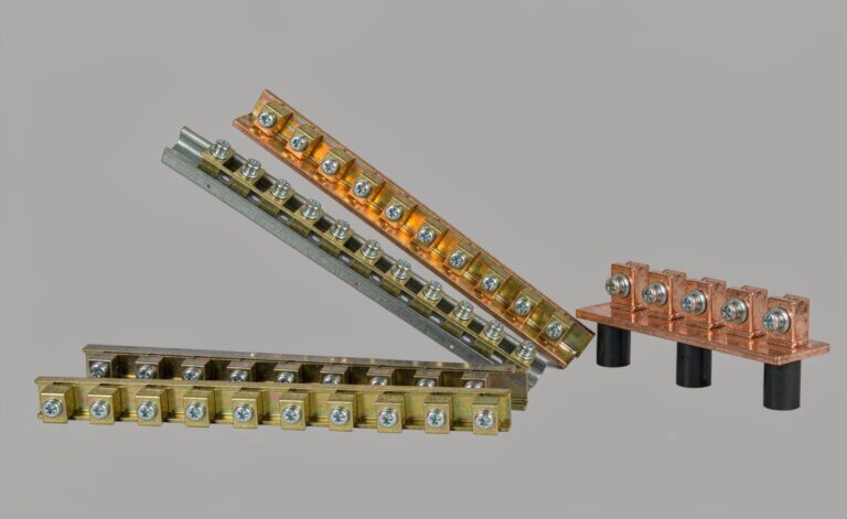
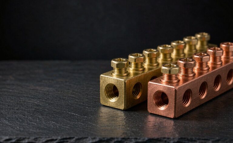
Brass bars with nickel-plated surfaces are common in this role because they resist the oxidation that raises joint resistance over years of thermal cycling. A brass bridge-type grounding bar suits cabinets that need three to fifteen positions on a compact footprint, while a double-row screw grounding bar handles higher circuit counts without growing the bar’s length.
Step 2: Choose the Mounting Location
Most manufacturers pre-punch or pre-drill mounting positions on the enclosure backplane, sometimes covered by a knockout you tap out with a screwdriver. Use them. They place the bar outside the wiring gutters, clear of the branch-circuit busbar stabs, and within reach once conductors are routed.
A location is wrong if it requires a custom hole, sits inside the bend radius of existing conductors, or forces EGCs to cross live parts on their way in. In a crowded main panel, also confirm that adding the bar will not block the panel’s listed wiring space — fill is a compliance issue as much as a neatness one.
Step 3: Prepare the Contact Surface
Powder coat and paint are insulators. NEC 250.12 requires nonconductive coatings such as paint, enamel and lacquer to be removed from threads and contact surfaces, or the connection to be made with fittings designed so removal is unnecessary. In practice you either scrape the contact pad down to bright metal, or fit an external-tooth star washer under the screw head and let the teeth bite through the coating as you torque.
Then take the file to any burrs left by knocking out the mounting knockout. A sharp edge inside a panel is a long-term insult to conductor insulation, especially on the bare-copper EGCs you are about to route to this exact spot.
Step 4: Mount and Bond the Bar
Set the bar on the prepared position and start the screws by hand to avoid cross-threading. If you are using a screw-terminal grounding bar with an insulating cover, confirm which part of the assembly is intended to touch bare metal — covered designs often rely on a designated bonding point rather than the whole body.
Tighten the mounting screws with real force. In a metal enclosure the bar must be bonded to the cabinet: the cabinet itself is part of the equipment grounding path. Where the bar is fitted on insulated standoffs — common in control panels where an isolated ground is specified — the bar instead receives a dedicated bonding jumper sized for its function, landed as its own listed connection.
Step 5: Terminate the Grounding Conductors
Route bare copper or green-insulated EGCs to the bar along the panel’s sides, keeping them out of the busbar area. Strip each conductor to the length the bar’s wire guide implies — enough that no insulation sits under the screw, not so much that bare copper extends past the terminal. Insert fully, then tighten.
One conductor per terminal unless the bar is explicitly marked for more. This is where many field installations fail inspection: the same connection that looks tidy with two wires under it was listed and tested with one.
Neutrals do not belong on this bar and EGCs do not belong on the neutral bar. NEC 408.40 requires the equipment grounding terminal bar to be bonded to the metal cabinet, and prohibits terminating EGCs on the neutral terminal bar (with the narrow exceptions in 250.142 for services and separately derived systems). If you are unsure which bar in front of you is which, read our breakdown of the difference between a neutral bar and a ground bar before landing anything.
Step 6: Torque to the Manufacturer’s Value
NEC 110.14(D) requires terminals to be tightened to the torque values specified by the manufacturer, using a calibrated tool where the specification calls for it. There is no single correct number to memorize: a #14 terminal position and a #2 position on the same bar can have different values, and two brands of bar with the same wire range routinely differ.
The numbers circulating online for “typical” ground bar torque should be treated as nothing more than a sanity check. Read the value off the bar marking, the panel’s label, or the kit instructions, set your torque driver to it, and work every terminal. Loose terminations are the most common cause of the heating failures described in our guide to why busbar and terminal connections overheat — the failure starts at the weakest joint, not at the conductor.
Main Panel or Subpanel: The Bonding Difference
Before you close the cover, get this right, because it determines what every later measurement should read. In service equipment — the main disconnect — neutral and ground are bonded at a single point through the main bonding jumper (usually a green screw or a strap). In a downstream subpanel they must be isolated: the neutral bar floats on insulated standoffs, and the ground bar bonds to the cabinet.
Condition
Main / service panel
Subpanel
Neutral-to-ground bond
Present, via main bonding jumper
Removed; bonding screw or strap not installed
Ground bar to enclosure
Bonded metal-to-metal
Bonded metal-to-metal
Neutral bar to enclosure
Bonded
Isolated on standoffs
Expected N–G continuity
Continuity present, low resistance
No continuity (open)
Neutral conductors also have their own rule worth remembering while you are in here: NEC 408.41 requires each neutral conductor to terminate in an individual terminal. Two neutrals sharing one point risks disturbing another circuit’s neutral when one is removed later.
Step 7: Verify Before Re-energizing
With the main breaker still off and the panel confirmed dead, set your multimeter to the lowest resistance range and test:
Bar to enclosure: should read near zero — this confirms your paint removal and metal-to-metal bond worked.
Ground bar to neutral bar (main panel): expect a low reading, typically well under 1 Ω in practice, confirming the main bonding jumper is installed and effective.
Ground bar to neutral bar (subpanel): expect open, confirming you removed the bonding screw or strap.
Those resistance figures are field-practice expectations, not NEC limits — the Code does not set a numeric pass value for this test. Treat them as a screen for gross errors: an open reading where continuity belongs, or continuity where isolation belongs, is a definite fault to chase down before restoring power. Your AHJ and the panel manufacturer’s instructions remain the authority.
Finish with a visual check — every conductor seated, no stray strands, no insulation pinched, cover screws reinstated — then re-energize and label the panel directory.
Mistakes That Fail Inspection
Mistake
What actually goes wrong
Correct approach
Mounting with sheet-metal screws
Shallow self-cut threads lose continuity under vibration and heat cycling; not a permitted method under 250.8(A)
Machine screws engaging at least two threads, or secured with a nut
Bar mounted over paint
Coating insulates the bar from the cabinet it must bond to
Scrape to bare metal or fit toothed bonding washers per 250.12
Two conductors per terminal
Joint was listed and tested for one; the second is unproven
Use a terminal identified for multiple conductors, or add capacity
EGC landed on the neutral bar
Violates 408.40
Land EGCs only on the equipment grounding terminal bar
Bar left unbonded in a metal cabinet
No fault return path; enclosure can become energized
Bond bar to cabinet, or fit a listed bonding jumper
Terminals tightened “by feel”
Under-torqued joints heat; over-torqued ones crack or strip
Torque to the manufacturer’s printed value under 110.14(D)
No spare capacity
Next circuit gets double-lugged or left ungrounded
Specify at least 20% more ways than today’s circuit count
FAQ
Can I add a second ground bar to the same panel?
Yes, when the enclosure has the space and the added bar does not obstruct listed wiring space. Every bar you install must still satisfy the same bonding requirement: it has to be electrically connected to the metal cabinet or to the equipment grounding conductor feeding the panel. Adding a second bar is common when the original runs out of terminal positions.
Does a ground bar have to be bonded to the enclosure?
In a metal cabinet, yes — NEC 408.40 requires an equipment grounding terminal bar to be bonded to the cabinet. The exception is the intentionally isolated case, such as an isolated-grounding arrangement built to a specific design, where the bar is insulated from the cabinet and grounded at a defined single point instead.
Can I drill my own mounting holes?
Avoid it. Panels are not designed for random penetrations: you risk striking conductors behind the backplane, and you compromise the enclosure’s structural integrity and listed construction. Use the manufacturer’s pre-punched positions, or the mounting pattern the panel label specifies.
What size ground bar do I need?
Count every branch circuit EGC you terminate today, add the circuits you plan to add, then choose a bar with roughly 20% more terminal positions than that sum. The bar’s conductor range also has to cover the smallest and largest EGC you land, and its listing has to cover aluminium if any of your grounding conductors are aluminium.
Why does my continuity test read open between the new bar and the neutral bar?
In a subpanel that reading is correct and desirable — it means the neutral is properly isolated. In a main panel it means the main bonding jumper is missing or loose, or your new bar is not making metal-to-metal contact with the enclosure. Do not fabricate a bonding jumper; check for the bonding screw or strap supplied with the panel and install the correct part.
In Short
A ground bar is a simple part doing unforgiving work. Match it to the panel, mount it on bright metal with listed hardware engaged at least two threads, keep one conductor per terminal unless the bar says otherwise, torque to the manufacturer’s number rather than intuition, and verify continuity before the cover goes back on. Get the main-panel versus subpanel bonding decision right and everything else follows.
Working to a specification rather than a one-off repair? Bars are available in defined way counts, conductor ranges and custom drilling patterns — specify them against your circuit schedule rather than adapting whatever is on the shelf.
Four constraints determine neutral bar size: terminations needed, unbalanced current per NEC 220.61, largest conductor and mounting centres — with real dimension charts.
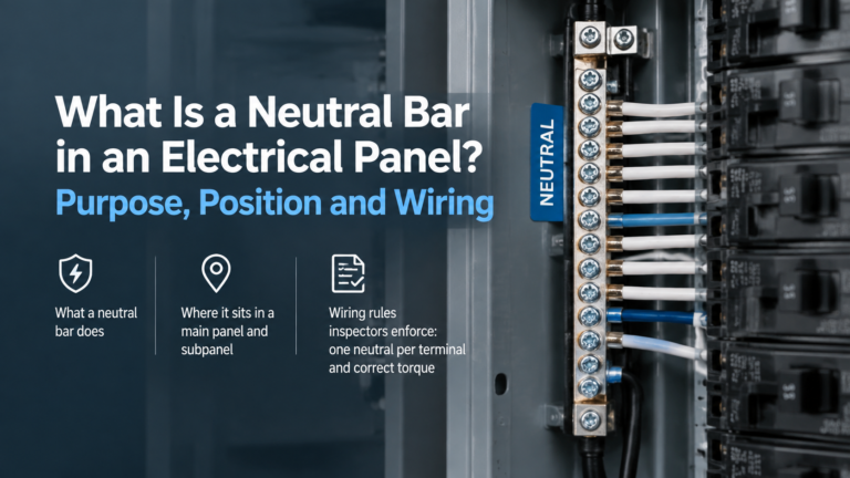
The neutral bar is the return path for every line-to-neutral load. How it works, where it sits, when it must be isolated from the enclosure, and the rules that govern it.