Comb Busbar Wiring Diagram for Distribution Boards: Pin vs Fork, Phase by Phase
Published: Author: Rachel
This guide works through the comb busbar wiring diagram for every pole count, the tooth-by-tooth phase assignments, and the differences between pin type and fork type terminals.
A comb busbar looks like it removes every opportunity to wire a board wrongly. The teeth are fixed, the pitch is fixed, the phases are pre-assigned inside the insulation — what is left to get wrong? Rather a lot, as it turns out, and the failures are rarely visible from the front of the board. A three-phase motor that runs backwards, a neutral borrowed from the wrong side of an RCD, an exposed cut end where a metre bar was shortened: all three are comb busbar errors, and none of them announce themselves.
This article is a wiring reference rather than a selection guide. It maps tooth position to phase for each common configuration, shows how pin and fork profiles meet the breaker terminal differently, and sets out the boundaries where a comb busbar must not be run continuously across a board. For choosing between profiles, see pin type versus fork type busbar; for whether a comb bar is the right method at all, see comb busbar versus jumper wire.
Working from a comb busbar wiring diagram is the only reliable way to land the phases correctly, because the tooth positions are fixed by the moulding and cannot be adjusted in the field.
The Quick Answer
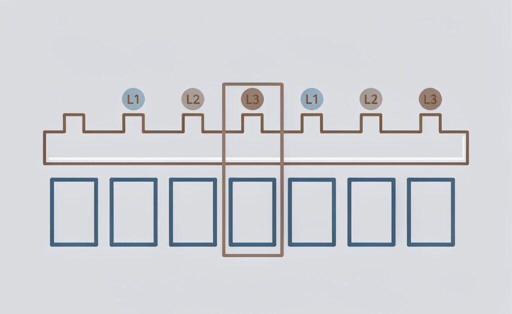
On a multi-phase comb busbar, the phase assignment cycles along the strip at the tooth pitch: every tooth belongs to a phase, and the sequence repeats every two, three or four teeth depending on the bar. Your job when wiring is not to choose the phase — the bar has already done that — but to place each breaker so that the tooth it lands on is the phase it needs. Get the starting offset wrong and every device downstream is on the wrong phase in the same systematic way. That is why the offset, not the wiring, is what you check first.
Pitch, Module and Why the Number Keeps Changing
Teeth are formed on a 17.8 mm or 18 mm pitch to match the standard circuit breaker module. The two figures appear interchangeably in catalogues, and both fit the same DIN rail — the difference is the manufacturing tolerance band rather than a different product standard. A one-metre bar carries 54 modules, which is where the “54-pole” designation in part numbers comes from.
Dimension
Typical value
What it sets
Tooth pitch
17.8 or 18 mm
Which breakers will physically align
Tooth width
4 to 5 mm
Contact area in the terminal
Tooth length
about 12 mm
Insertion depth into the terminal
Modules per metre
54
How many single-pole ways one bar feeds
Note the mismatch risk: a breaker that occupies two modules covers two teeth, and a three-pole breaker covers three. The bar does not adapt to the device. The device lands on whatever teeth are under it, and if the device is one module narrower or wider than you assumed when you laid out the rail, everything after it shifts by one tooth — which on a three-phase bar shifts everything after it by one phase.
Single-Phase Bars: One Phase, Many Teeth
A 1-phase bar is the trivial case: every tooth is the same phase, so no offset error is possible. It is used to distribute one phase, or one pole of a supply, to a row of single-pole protective devices. The wiring question here is not which tooth but which end is fed, because the current path runs the full length of the bar from the feed point — covered in detail in comb busbar current rating.
Where boards use 1-phase bars in pairs or triples for a three-phase supply, each bar carries one phase and the three bars are stacked side by side. This is common on compact boards and on ranges where the manufacturer does not offer a multi-phase comb. It uses three times the rail depth of a single 3-phase comb, but it makes phase identification explicit and it lets you change one phase without disturbing the others.
Two-Phase Bars: The Alternating Pattern
On a 2-phase bar the teeth alternate, so the assignment is fixed by the tooth number alone:
Tooth number
1
2
3
4
5
6
7
8
Phase
L1
L2
L1
L2
L1
L2
L1
L2
Odd / even rule
Odd teeth are L1, even teeth are L2
The practical use is a single-phase supply split into two protected poles, or a two-phase feed to equipment that does not require a neutral. Where a 2-phase bar is used to feed 1-pole plus neutral devices, check the device’s own terminal arrangement — the neutral pole of the device may be on the same side as the phase pole or offset from it, and the bar has to match.
Three-Phase Bars: Where Offset Errors Live
This is the configuration that produces the expensive mistakes. The sequence repeats every three teeth:
Now the two placements that matter. A three-pole breaker occupying teeth 1 to 3 receives L1, L2, L3 in order — correct. The same breaker starting at tooth 2 receives L2, L3, L1. Electrically the device is still fed from all three phases, so nothing trips and nothing looks wrong. But for any rotating load the phase sequence at the motor terminals has rotated, and the motor turns the wrong way. This is the classic three-phase comb busbar error and it is invisible until something spins.
The second placement is a row of single-pole breakers on a 3-phase bar. Teeth 1, 2 and 3 give L1, L2, L3, so three adjacent single-pole circuits are automatically spread across the phases. That is the desirable outcome for balance, and it is one of the genuine advantages of a 3-phase comb: distributing single-phase loads evenly is the default result rather than something the installer has to remember. The pin type 3-phase busbar and C45 type 3-phase busbar both follow this pattern on an 18 mm pitch.
Four-Phase Bars: Where the Neutral Runs Too
A 4-phase bar adds a neutral pole to the cycle, so the sequence repeats every four teeth:
Tooth number
1
2
3
4
5
6
7
8
Assignment
L1
L2
L3
N
L1
L2
L3
N
Rule
Every fourth tooth is neutral; a four-pole breaker starting on tooth 1 receives L1 L2 L3 N in order
The four-pole comb is what you want for boards feeding a mix of three-phase and single-phase loads where each outgoing way needs its own neutral at the device. It also creates the boundary condition described below: a neutral carried on the comb is a neutral that belongs to the comb, and it cannot be shared with circuits that are protected by a residual current device upstream of the bar. Both the pin type 4-phase busbar and the C45 4-phase busbar are built on this pattern.
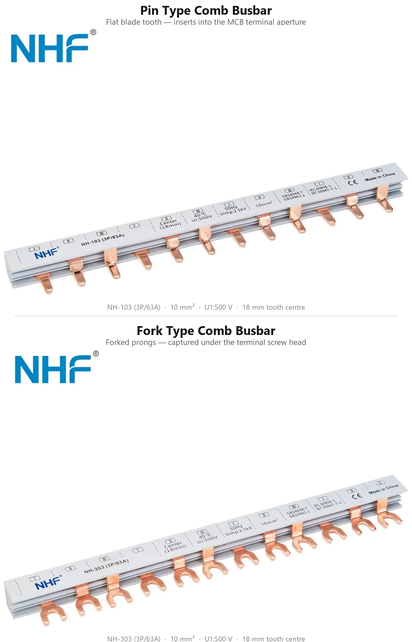
Pin Versus Fork at the Terminal
The tooth profile decides how the connection is physically made, and the two profiles do not meet the same terminal hardware.
Aspect
Pin type
Fork type
Terminal it fits
Cage clamp or tunnel terminal
Screw terminal with a pressure plate
How it seats
Pin is inserted into the clamp, then the screw is tightened onto it
Fork slides under the loosened screw head, then the screw is tightened
Visual confirmation
Poor — seating depth is hidden inside the terminal
Better — the fork is visible on the screw shank before tightening
Failure mode if mis-seated
Partial contact area, no external sign
Fork can sit proud or be pushed out during tightening
Typical range
1 to 4 phase, 32 to 125 A
1 to 3 phase, same current ladder
The row on visual confirmation is the one that causes field problems. A pin that has not gone fully home looks identical to one that has, from the front of the board. The only reliable checks are resistance — the tooth should not pull out with a firm tug before the screw is tightened — and, after energising, thermal imaging under load. Fork types give the installer a visible cue, which is why they remain popular on boards that are assembled on site rather than in a factory.
Where a Comb Busbar Must Not Run Continuously
The biggest wiring error is not a misaligned tooth. It is running one bar across a boundary that should separate two parts of the board. Three boundaries matter:
Boundary
Why the bar must stop
What to do instead
Downstream of a residual current device
Every conductor leaving an RCD, neutral included, must pass through it. A neutral carried on a bar fed from upstream bypasses the device and it will not detect the imbalance correctly.
Feed RCD-protected ways from a separate bar downstream of the device, or use devices with the neutral switched and terminated at the device.
Across a section with a different supply source
Two sources — mains and generator, or mains and inverter — must not be paralleled through a shared bar.
Separate bars per source, interlocked at the changeover device.
Across a metering or monitoring point
Current taken off upstream of a meter is not measured; taken off downstream of a protection device it may not be protected.
Break the bar at the measurement point and feed the second section separately.
On the first row, the underlying principle is the same one that governs panel neutral conductors: the return path has to follow the same route as the outgoing path, or protection stops working. The neutral bar versus ground bar article covers why that separation matters in a panel, and the same logic applies at board level.
Feeding the Bar: Position and Hardware
Where current enters the bar is a wiring decision, not just a rating one. Feeding at the end sends all current down the full length; feeding at the centre splits it into two half-length paths and roughly doubles the current the bar can carry. The full derivation is in comb busbar current rating — the practical upshot is that the feed terminal is a specified component with its own clamping range, and it has to be ordered with the bar.
Feed terminals come in a few forms: a direct-feed clamp that lands a large conductor on the copper at a chosen point, a module that occupies one or two breaker spaces and accepts the supply conductor, or a low-profile version where depth is tight. Match the terminal’s conductor range to the incoming cable, not to the bar rating — they are different numbers.
Cutting, Ends and Finishing
Cut between teeth, on the pitch, and deburr. Cutting through a tooth leaves a partial pin that will not seat and may bridge to its neighbour. After cutting, fit the matching end cap: the finger-safe claim on the product depends on every exposed end being closed, and caps are a separate item in the busbar accessories range.
Check before cutting that the removed length does not change the phase alignment of the remaining teeth. On a 3-phase bar, removing three teeth keeps alignment; removing one or two rotates every subsequent device by one or two phases. If you must cut off a non-multiple number of teeth, re-establish the alignment at the feed end rather than assuming it survived.
Pre-Energisation Checklist
Check
How to verify
Profile matches the breaker terminal
Pin for cage clamp, fork for screw terminal — confirm on one device before fitting the whole row
Pitch matches the breaker series
Dry-fit the bar across the full row without tightening; every tooth should align
Phase offset is correct
Identify tooth 1, confirm the first three-pole device starts on an L1 tooth
Every tooth is seated
Tug test before tightening, then torque to the breaker manufacturer’s figure
Cut ends are capped
One cap per cut end, correct profile
Feed terminal matches the conductor
Clamping range covers the incoming cable size
Boundaries are respected
No bar crosses an RCD, a source changeover, or an unmetered section
Phase sequence confirmed
Rotation check at the load before connecting any motor
Where to Start on the Product Side
The busbars below cover the pole counts and tooth pitches described in this guide. Each is a comb busbar with copper conductors, and the feeder connection hardware for the incoming supply is listed alongside them.
Can I use a 3-phase busbar for single-phase circuits only?
Yes, and it is good practice — three adjacent single-pole breakers land on L1, L2 and L3 automatically, which spreads the load across the phases without the installer having to think about it. The caution is that any three-pole device on the same bar must start on an L1 tooth, or its phase sequence will be rotated.
Why did my motor run backwards after I changed the busbar?
Almost always a one-tooth offset. A three-pole breaker starting on tooth 2 instead of tooth 1 receives L2, L3, L1 rather than L1, L2, L3. Nothing trips and nothing is visibly wrong; the phase sequence at the motor has simply rotated. Swap any two phases at the load, or re-index the bar so the device starts on an L1 tooth.
Can I join two comb busbars to make a longer run?
Not by butting them together. There is no published rating for a joined pair, the joint itself becomes an untested connection in the current path, and the insulation profile is interrupted. Use a bar long enough for the run, or feed each section separately from a common feeder terminal.
Do I need a neutral on the comb bar?
Only if the outgoing devices need a neutral at each way. Many boards run a phase comb and terminate neutrals on a separate neutral bar, which is simpler and avoids the RCD boundary problem entirely. Use a 4-phase comb where each outgoing device genuinely needs its own neutral pole.
What happens if a tooth does not align with a breaker?
Do not force it. A tooth that has to be bent to reach a terminal will not seat correctly, and the resulting partial contact is a hot joint waiting to develop. The bar and the breaker series are not matched — confirm the pitch and the series before assembly, which is what the compatibility guide walks through.
The Bottom Line
A comb busbar fixes the phase of every tooth, which means wiring a board with one is a layout problem rather than a connection problem. Place each device so the teeth under it carry the phases it needs, confirm the first three-pole device starts on an L1 tooth, match the tooth profile to the terminal hardware, cap every cut end, and do not let the bar cross an RCD or a source changeover. Do those five things and the comb does what it is supposed to do: make a whole row of terminations consistent, repeatable and hard to get wrong. The remaining checks — current rating and feed position — are covered in comb busbar current rating.
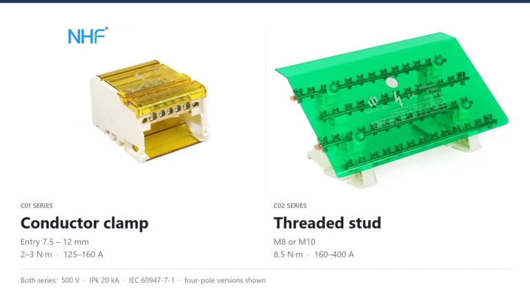
Both ranges are rated 500 V and IPk 20 kA, so the data sheet cannot choose for you. The difference sits at the input terminal: a conductor clamp with a published conductor range, or a stud that holds a cable lug.
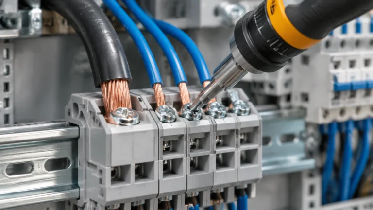
Four rules decide whether a terminal block joint runs cool or overheats: the strip length the block specifies, the separate input and output torque values, one rated conductor per clamp, and the conductor range for the ferruled size.
How to test earth continuity on a grounding bar: the dead test method, instrument and test current selection, acceptance values in ohms, and the parallel-path mistake that invalidates results.