An earth continuity test is the measurement that proves a protective earth path actually exists, and that it is low enough in resistance for the protective device to clear a fault in the required time. Get it wrong in either direction and the consequences are serious: a path that reads too high means the protective device may never trip, and a path that reads too low means you have accepted a reading that was never really tested. This guide covers the method, the instruments, the acceptance values and the mistakes that produce wrong numbers. It is written for reference, and the actual test has to be carried out by a competent person under the wiring rules that apply in the jurisdiction where the installation sits.
Every acceptance figure quoted below comes from a published standard or a commissioning procedure, and every product dimension comes from our own published data.
What the earth continuity test actually proves
The test confirms that every exposed conductive part is bonded to the main earthing terminal through a path of low enough resistance. That is the whole point of the protective earth arrangement. When an insulation fault occurs, the fault current needs a low-impedance route back to the supply so that the protective device operates and clears the fault within its required disconnection time. The separation between the neutral and the protective earth path is covered in our guide on putting a ground wire on a neutral bar, and the bar types themselves in types of neutral bar.
Think about what happens when that path is interrupted or too resistive. The fault current cannot flow as intended, the device does not clear the fault within the permitted time, and the exposed metalwork stays at an liftd voltage. A person touching the equipment then becomes the lowest-resistance path to earth. This is why the continuity test is a life-safety measurement and not a paperwork exercise.
There is a second reason it matters that is less obvious: a high-resistance earth path also prevents the protective device from operating correctly under an earth fault, which in turn means the equipment can be left in service with a latent fault that nobody notices until it is exercised.
Two tests that are often confused
The most common confusion in this area is between a dead continuity test and a live loop impedance test. They answer different questions, use different instruments, and produce numbers that are not interchangeable.
Earth continuity test
Earth fault loop impedance test
Supply state
Isolated and locked off
Energised
What it measures
Resistance of the protective conductor itself
Total impedance of the fault loop
Typical instrument
Low-resistance ohmmeter, or a multifunction tester on the continuity range
Loop impedance tester
Test current
DC, at least 200 mA; 10 A or more on a dedicated DLRO
A known load applied for roughly 20 ms
Answers
Is the conductor intact and properly terminated?
Will the device clear a fault within the required time?
Both have to pass. A perfect continuity reading does not prove the loop impedance is within limits, and a good loop impedance reading does not prove every conductor is properly terminated. They are complementary checks, and a commissioning schedule that only runs one of them has a gap in it. For why the two bars must be kept apart in the first place, our neutral bar versus ground bar guide sets out the wiring rules.
The procedure
Steps 1 and 2: isolate, prove dead, and break the parallel path
Dead testing is the only reliable way to measure continuity, because a parallel path through the live network reads artificially low and hides exactly the fault you are looking for. Lock off and tag the isolator, then confirm zero voltage with a two-pole voltage tester before touching any conductor. For how the bar itself should be mounted and bonded in the first place, see our guide to installing a ground bar in an electrical panel.
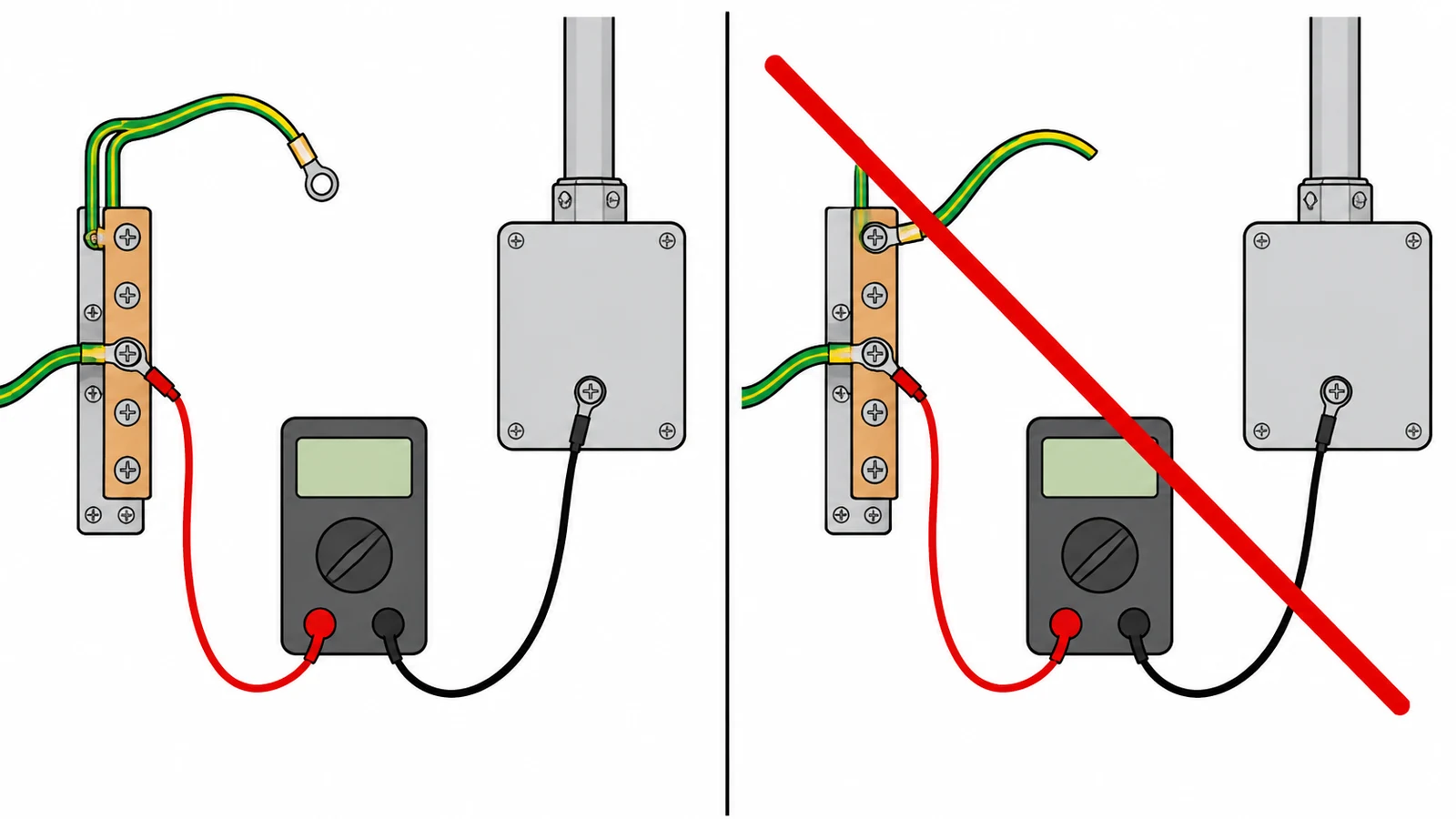
Next, disconnect one end of the conductor under test.
This is the step that most often gets skipped, and it is the one that invalidates the whole test. If the conductor is still connected at both ends, current can flow through alternative metallic paths such as conduit, cable armour or a bonded enclosure, and the meter will read a value that looks fine but proves nothing about the conductor you are testing.
Disconnect at one end and test from the disconnected end to the metalwork on the far side of the clamp. Where possible, isolate at the consumer unit so that the entire bonding run is in the measured path.
Step 3: clean the contact surfaces
Surface oxide on a copper conductor or a landing point can add several ohms of apparent resistance on its own. Clean the contact face of the conductor and the clamp before making the measurement, and re-tighten any joint you disturbed. A reading that fails is often a dirty contact, not a damaged conductor, and the distinction matters when you write the report.
Step 4: null the test leads
Short the two leads together and confirm the instrument reads zero. If it does not, subtract the lead resistance from every reading you take. On a long run this is not a refinement, it is the difference between a passing and a failing result, because test lead resistance is typically of the same order as the value you are trying to measure.
Steps 5 and 6: measure, record, then reconnect and re-torque
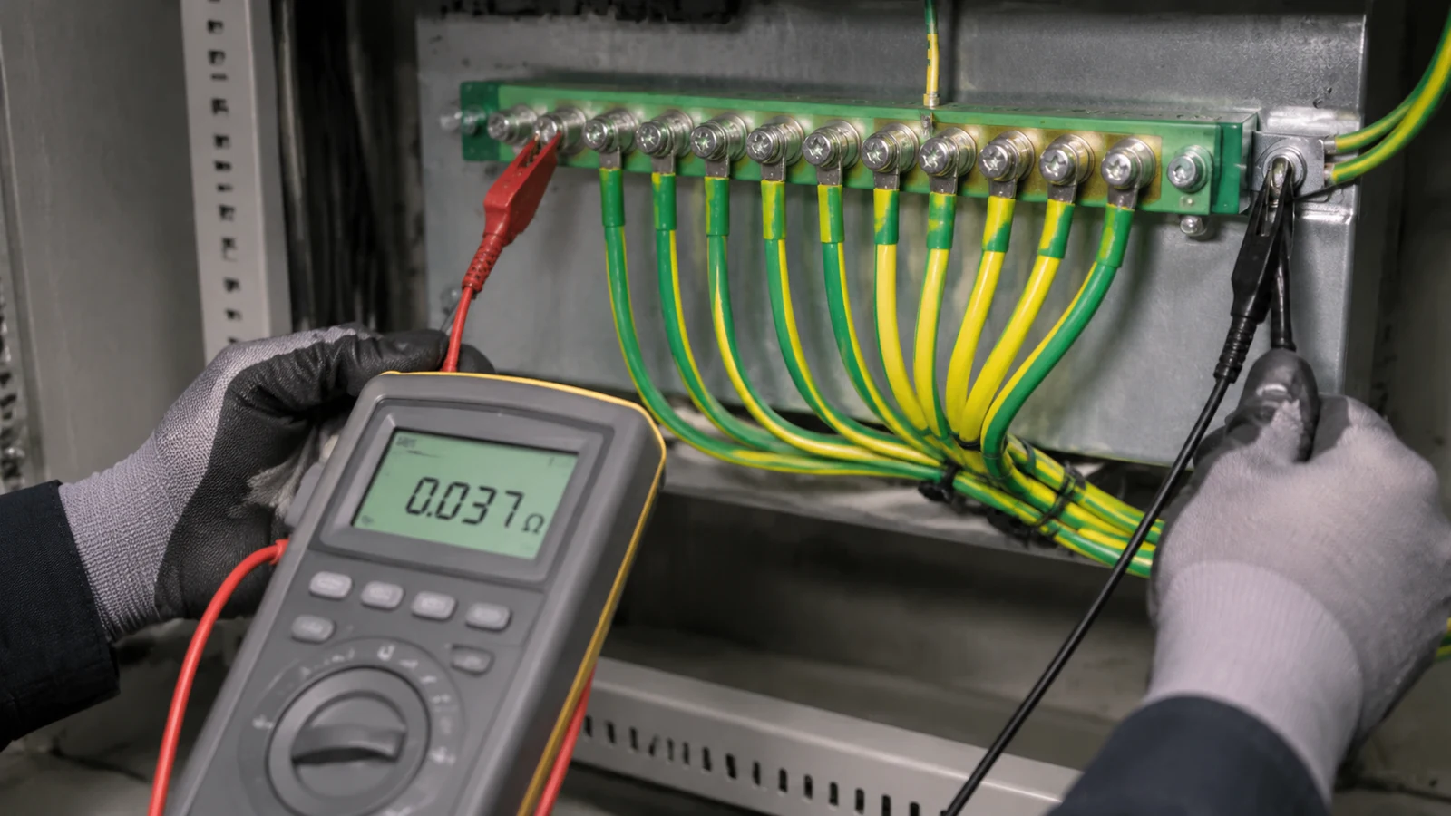
Place one lead on the disconnected conductor and the other on the metalwork as close as possible to the bonding clamp, so that the clamp itself is inside the measured path. Record every reading individually, along with the instrument serial number and the test mode used, because results are mode-dependent and a dispute usually turns on exactly those details.
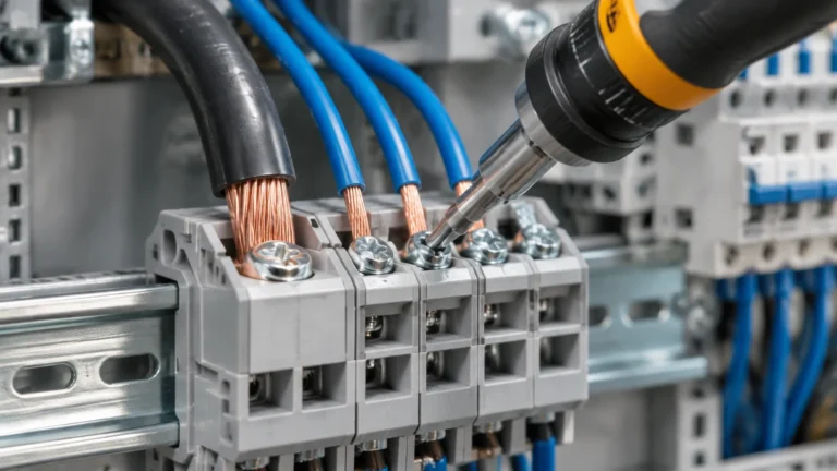
Reconnect the conductor and torque it to the manufacturer’s value. A connection tested and then left loose is worse than one never tested, because the test record will now claim a value that no longer exists. Our A04E earth bar with green fixing part and the A27E screw terminal grounding bar with cover are supplied with the conductor, screw size and hole diameter specified for each way count, so the torque value comes from the product data rather than guesswork.
Choosing the right instrument and test current
The test current matters because it determines whether the measurement can reveal a degraded joint. A low-resistance ohmmeter injecting at least 200 mA is enough to confirm a conductor is continuous, which is the requirement for portable appliance and supplementary bonding checks.
For bonding on a distribution installation, a higher current gives a more representative picture of the joint under working conditions. A dedicated low-resistance ohmmeter injecting 10 A or more will develop enough voltage across a marginal joint to break down the oxide film and give a true reading rather than a flattering one. Where a loop of the protective conductor is being verified in a substation or a main earthing system, a 10 A instrument is the appropriate choice.
The instrument matters as much as the current. A general-purpose multimeter on the lowest ohms range will read a value that includes the lead resistance and its resolution may be too coarse to distinguish 0.03 Ω from 0.08 Ω. A multifunction installation tester with a dedicated continuity range, or a low-resistance ohmmeter, avoids both problems.
Acceptance values
There is no single universal pass mark, because the correct limit depends on what you are measuring and which device is supposed to clear the fault. The values below are grouped by what is being verified.
What is being measured
Typical acceptance
Notes
Protective bonding conductor continuity
Not more than 0.05 Ω
Any reading above this is treated as non-compliant
Complete conductor run including joints
0.1 Ω or less
Micro-ohmmeter or low-resistance tester
Equipotential bonding between conductive parts
0.2 Ω or less
Potential difference between parts not more than 50 mV dry, 10 mV damp
Conductor connection resistance
Under 0.05 Ω
Checked with a micro-ohmmeter plus thermal imaging
Standalone earth electrode resistance
Typically 10 Ω maximum
Where a TT system requires an electrode test rather than a loop test
Earth fault loop impedance
Against the maximum permitted for the device
Calculated from the supply voltage and the device operating current
The loop impedance limit is derived rather than tabulated. The maximum permitted earth fault loop impedance Zs is the phase voltage divided by the minimum operating current of the protective device. For a 230 V circuit protected by a 32 A Type B device operating at 5 × In, that is 160 A, so the maximum Zs is 230 ÷ 160 = 1.44 Ω. A Type C device of the same rating trips at a lower multiple of In and therefore has a correspondingly lower limit. The protective conductor’s own resistance counts directly against this budget, which is why a loose connection can push a compliant circuit over its limit.
For reference, a reading of 0.037 Ω across a bonding connection is comfortably inside the 0.05 Ω limit, while a reading of 0.3 Ω on the same joint would be more than six times the limit and would need to be investigated before energising.
Torque, corrosion and mechanical checks
Continuity is a snapshot, and a good reading does not mean the joint will stay good. Two mechanical checks belong alongside it.
Check the tightening torque on every terminal. A bond that has been tightened to the manufacturer’s value stays tight; one that has been finger-tightened will move under thermal cycling. Typical reference values run to at least 15 N·m for an M10 bolt. Our A04E and A14E grounding bars specify their screw sizes and hole diameters for each way count, so the correct torque can be quoted against the specific product rather than assumed.
Check the corrosion protection. A galvanised coating on a steel component should be at least 65 μm, and this is worth confirming on any bar that has been stored, shipped in a damp container, or installed in a corrosive or coastal environment. The D02 brass bridge type grounding bar and the D05 double row screw bridge type grounding bar use brass with a nickel-plated surface and a galvanised steel screw, which is a combination chosen for exactly this reason.
Note also that the housing material and operating range differ across our earth bar families, and the range matters in a hot enclosure. The A04E and A14E grounding bar with full plastic cover use ABS housings rated from −20 °C to 70 °C, the A27E series uses PA66 nylon rated from −30 °C to 110 °C, and the D02 and D05 bars are brass with a nickel-plated surface. Where the enclosure runs hot, the higher-rated housing is the correct choice.
Six mistakes that produce a wrong reading
Leaving the conductor connected at both ends. The most consequential error, and the one that turns a failed joint into a passing test. A parallel path through conduit or armour reads lower than the conductor you are testing.
Not nulling the test leads. On a long run, lead resistance can exceed the value you are trying to measure.
Testing on a live installation. Parallel paths through the live network produce an artificially low reading.
Skipping the contact cleaning. Oxide on a landing point adds apparent resistance that has nothing to do with the conductor.
Measuring to the nearest convenient earth point. Place the probe as close as possible to the clamp under test, so the clamp is inside the measured path rather than outside it.
Trusting a reading taken immediately after heavy rain. Saturated soil gives an unrepresentatively low electrode resistance, which is a separate measurement from continuity but is often taken on the same visit and recorded without the caveat.
Testing a bar you did not install
Continuity testing comes up in three situations, and the approach differs in each.
At commissioning. The full dead test described above, on every bonding run, with the loop impedance test alongside it. This is the point at which the whole installation is proven.
At periodic inspection. A sampling regime rather than a full retest. The joints most likely to have degraded are the ones that were disturbed, exposed to moisture, or terminated under a different crew. A rising trend on a particular bar across successive inspections is more informative than any single absolute value.
After a modification. Any work that interrupts the earth path, adds a new enclosure, or changes the supply arrangement. Extending a circuit, adding an inverter, or replacing a panel means the bonding arrangement has changed and needs proving again. Where a new piece of equipment has been added, its own earth terminal and bonding conductor are tested as part of that work, following the same procedure.
Two situations need particular care. Where a cable armour or a metal conduit has been used as the protective conductor, the continuity test is the only thing that confirms the armour is continuous along its whole length and terminated at both ends, because the armour itself is not visible. And where a bar has been extended by bolting a second bar to the first, that bolted joint between the two bars has to be included in the measured path, not just the conductor landings on each bar.
What to record
A continuity test result is only useful if the sheet behind it can be audited later. For each measurement record the test point description, the measured value, the instrument used with its serial number, the test mode, whether the leads were nulled, and whether the conductor was disconnected for the test. Then record the tightening torque applied on reconnection and the date.
That sheet is also what lets you compare against the previous test, and a rising trend on a particular joint is a meaningful signal well before any single reading fails its limit. Where the reading is unexpectedly high, the step that usually explains it is the connection itself rather than the conductor, which is where the bar selection matters: our A27E and D06 pure copper neutral bar families are both available with the conductor size and hole diameter matched to the run being landed. Sizing the bar for the number of ways you need is covered in our neutral bar size chart.
Frequently asked questions
What resistance should an earth continuity test read?
For a protective bonding conductor, not more than 0.05 Ω. For a complete conductor run including its joints, 0.1 Ω or less. For equipotential bonding between conductive parts, 0.2 Ω or less. The value that matters most is the one that verifies the bonding run between the equipment and the earth bar.
Do I have to disconnect the conductor to test it?
Yes, unless the measurement is being taken as part of a documented method that accounts for parallel paths. Leaving the conductor connected allows current to flow through conduit, armour or bonded metalwork, and the reading will be lower than the true resistance of the conductor under test. It is the most common reason a failed joint passes a test.
What test current should I use?
At least 200 mA for continuity and supplementary bonding checks, which is the standard requirement for low-resistance ohmmeters. For bonding on a distribution installation or main earthing system, 10 A or more gives a more representative reading of the joint.
Can I use a normal multimeter?
For a quick check, yes. For a commissioning record, no. A general-purpose multimeter on the lowest ohms range includes the lead resistance and may not resolve the differences that matter between a good joint and a marginal one. Use a multifunction installation tester on the continuity range or a dedicated low-resistance ohmmeter.
How is the maximum loop impedance calculated?
Maximum Zs equals the phase voltage divided by the minimum operating current of the protective device. For a 32 A Type B device on 230 V, operating at 5 × In, that is 230 ÷ 160 = 1.44 Ω. Type C devices trip at a lower multiple and therefore have a lower permitted value.
Does a low continuity reading mean my earthing is safe?
No. Continuity confirms one conductor run is intact and properly terminated. Whether the fault will clear in time depends on the total loop impedance, the protective device, and the condition of every other part of the path. It is one necessary check, not a complete verification.
Conclusion
An earth continuity test is simple to perform and easy to perform wrongly. Isolate the supply, disconnect one end of the conductor, clean the contacts, null the leads, measure from the disconnected end, and record the result with the instrument details. Then reconnect and torque to the specified value.
The two details that most often invalidate the result are leaving the conductor connected at both ends and forgetting to null the test leads. Everything else on the list is secondary. Get those two right and the numbers mean something.
Our grounding bar range covers 4 to 16 ways in the A04E and A14E families with ABS housings, 6 to 12 ways in the A27E series with a PA66 housing, and 3 to 15 holes in the D02 and D05 brass bridge-type bars. If you need the section, hole diameter and screw size for a specific way count, send the requirement and we will specify against it.
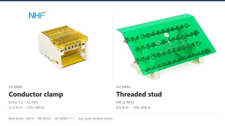
Both ranges are rated 500 V and IPk 20 kA, so the data sheet cannot choose for you. The difference sits at the input terminal: a conductor clamp with a published conductor range, or a stud that holds a cable lug.
Four rules decide whether a terminal block joint runs cool or overheats: the strip length the block specifies, the separate input and output torque values, one rated conductor per clamp, and the conductor range for the ferruled size.
How to size a copper busbar: the current density formula, DIN 43671 ampacity tables, IEC 61439-1 temperature rise limits, short-circuit withstand and voltage drop.