Busbar Sizing: How to Calculate Cross-Section and Current Rating
Published: Author: Rachel
Busbar sizing is where panel builders most often reach for a table and stop thinking. A table describes one set of conditions. Your panel has its own: ambient temperature inside the enclosure, permissible temperature rise, short-circuit duty, and how many bars sit next to each other. This guide sets out how to size a copper busbar properly, which standard actually governs the rating, and where the common shortcuts fail.
Every dimension and current figure quoted below comes from our own published product data or from the published standards themselves, not from a generic rule of thumb.
What busbar sizing actually has to answer
A busbar is a rigid conductor that carries current between the incoming device and the outgoing circuits. Sizing it is not one calculation but four separate questions, and they have to be answered in a fixed order because each one constrains the next.
Continuous current. What current must the bar carry indefinitely, after diversity and any margin for future load?
Temperature rise. How hot does the bar get at that current, and does it stay inside the permitted limit?
Short-circuit withstand. Does the bar survive the prospective fault current for the clearing time, thermally and mechanically?
Voltage drop. Over the run length, does the bar still deliver the supply voltage the loads expect?
Skipping to step two produces a bar that passes a formula and fails in service.
Current density is a starting point, not a rating
The most widely quoted sizing rule is the simplest one: divide the design current by an allowable current density to get the required cross-section.
A (mm²) = I (A) ÷ J (A/mm²)
For copper, typical design densities quoted for low-voltage switchgear sit between 1.0 and 1.6 A/mm². For aluminium, roughly 60 percent of that. These numbers get used so widely that they are often treated as if they were the rating itself. They are not.
Current density is a purely geometric ratio. It says nothing about how the conductor sheds heat. Actual ampacity is a thermal outcome: the balance between I²R losses generated in the conductor and the heat carried away by convection, radiation and conduction. The same cross-section in two different shapes carries two different currents, because the two shapes present different surface area to the air.
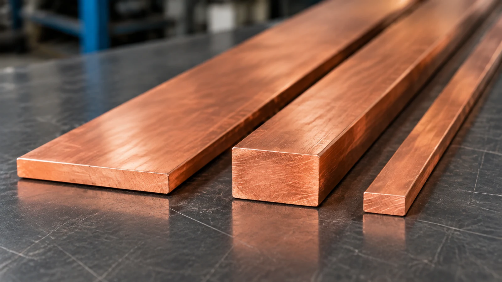
The clearest illustration uses two bars of identical area. A 100 × 10 mm bar and a 50 × 40 mm bar are both 1000 mm², but their perimeters are 220 mm and 180 mm. Under the same thermal assumptions the wider bar dissipates more heat and carries more current. Same area is not the same ampacity.
The same reasoning explains why adding parallel bars does not multiply the rating. The second bar shades the first, restricting the airflow between them, so each additional bar contributes less than the one before it. A second bar adds roughly 64 percent of the original rating, not 100 percent, and the third adds less again. A second bar also needs a deliberate gap between the bars; spacing them closer than the bar thickness removes most of the benefit.
This is why IEC 61439-1 does not prescribe a fixed current density as an acceptance criterion. It requires the finished assembly to be verified by one of three routes: a temperature-rise test, comparison with an already-verified reference design, or calculation. Density is a preliminary selection tool, not a compliance route.
DIN 43671 is the standard that actually carries the ratings
Because IEC 61439-1 works by verification rather than by tabulated current, most engineers end up looking for a table of rectangular copper bar ampacities. There is one that carries real authority, and it is a German standard: DIN 43671.
DIN 43671 defines continuous currents for rectangular copper bars at a reference ambient temperature of 35 °C and an average bar temperature of 65 °C. Values are tabulated for bare and coated bars, and a correction factor k₂ is provided to adjust them to other ambient and bar temperatures. The same dimensional series is used across the industry, so a 30 × 10 mm copper bar means the same section everywhere.
Two features of DIN 43671 are worth knowing because they are frequently missed.
The first is that the rating depends on surface finish. The tabulated values assume an emission level of 0.4, corresponding to an oxidised copper bar. A matte black non-metallic coating raises the emission level to around 0.9, and in the DIN 43671 tables the coated and uncoated figures for the same section differ by more than 20 percent. Copper Development Association Publication 22 reports the same effect independently, noting roughly a 20 percent gain from a black matt finish. Painting a bar is not only corrosion protection; it changes its rating.
The second is that the decisive temperature is not the bar’s own limit but the lowest permissible temperature of whatever touches it. A bar can sit well inside its own thermal limit and still be unsuitable if the cable lug or fuse base it connects to has a lower rating. DIN 43671 works on a 65 °C bar temperature for good reason: it leaves thermal reserve below the 85 °C level at which copper begins to anneal.
Bar section
Cross-section
Current, bare copper
Current, coated copper
20 × 5 mm
100 mm²
320 A
580 A
30 × 10 mm
300 mm²
573 A
676 A
40 × 10 mm
400 mm²
715 A
850 A
50 × 10 mm
500 mm²
852 A
1020 A
100 × 10 mm
1000 mm²
1490 A
1810 A
These are DIN 43671 reference figures at 35 °C ambient and 65 °C bar temperature, quoted as a comparison basis, not our products’ ratings. Ambient correction and the mounting arrangement still have to be applied on top.
The six-step sizing method
Steps 1 to 3: current, material and preliminary section
Start from the maximum continuous current the bar must carry, not from the sum of nameplate ratings. For three-phase loads, I = P ÷ (√3 × V × PF); for single-phase, I = P ÷ (V × PF). Then apply a diversity factor if the connected circuits will not all run at full load simultaneously, and add margin for future growth; for continuous loads a 25 percent margin is common practice.
Copper is the default for switchgear: smaller cross-section for the same current, reliable bolted joints without special treatment, and dimensional stability at practical thicknesses. Aluminium needs roughly 1.5 to 1.6 times the cross-section, and because its oxide layer forms immediately on an exposed surface, joints need plating or antioxidant treatment. Where weight is not the driver, copper usually wins on total installed cost.
Apply A = I ÷ J with a density appropriate to the material and to whether the bar sits in free air or inside an enclosure. Then select the next standard section at or above the calculated area.
Step 4: verify the temperature rise
This is where a density calculation stops being sufficient. Check the tabulated rating for the chosen section against your actual ambient and mounting condition.
IEC 61439-1 sets temperature-rise limits relative to a 35 °C daily average ambient, with an ambient that must not exceed 40 °C. The principal limits are:
Terminals for external insulated conductors: 70 K
Bare copper busbars and conductors: 105 K, a figure tied to the temperature above which copper starts to anneal
Accessible external enclosures and covers: 30 K for metal surfaces, 40 K for insulating surfaces
When the site ambient exceeds the 35 °C reference, the rating must be reduced. The commonly applied correction factors are approximately 0.91 at 40 °C, 0.82 at 45 °C and 0.71 at 50 °C. A bar selected from a table at 35 °C and installed in a 50 °C plant room without correction is the classic reason a correctly-sized bar still overheats.
Steps 5 and 6: short-circuit withstand and voltage drop
The bar must survive the prospective fault current for the duration the protective device takes to clear it. The minimum cross-section comes from the adiabatic expression:
A_min = I_k × √t ÷ k
where I_k is the prospective short-circuit current, t the clearing time in seconds, and k is a material constant: 122 for copper and 81 for aluminium when starting from 90 °C and ending at 200 °C. For other clearing times, scale the result by the square root of the ratio: multiply by 0.71 for a 0.5 second clearing time and by 1.73 for 3 seconds.
At high fault levels the mechanical forces on the supports, rather than heating, usually decide the design. The peak force on the middle bar of a three-phase system is calculated from the peak current, the spacing between supports and the centre spacing of the phases, and it rises with the square of the fault current. Support spacing therefore has to be derived from the force, not chosen by habit.
ΔV = I × (ρ × L) ÷ A
Voltage drop over the run is the final check. For copper, resistivity is about 0.0175 Ω·mm²/m at 20 °C and rises by roughly 0.4 percent for each degree above that. Over long runs this is where an otherwise correctly sized bar falls short, and the fix is a larger cross-section or a parallel bar rather than a smaller one.
Why MCB busbars and panel busbars are sized differently
Comb busbars, the type that links a row of MCBs inside a distribution board, behave differently from the flat bars discussed above. Look at the published cross-sections and currents from our range and the apparent current density is far higher than the 1.0 to 1.6 A/mm² quoted for panel busbars:
The apparent contradiction disappears once you recognise what limits the current in each case. A comb busbar is short, is clamped between the terminals of the breakers it feeds, and is not a free-standing conductor carrying the whole panel current along its length. Each tooth is a separate termination point, and the heat leaves through the terminal interfaces rather than along the bar. The rating that matters is the rating of the breaker terminal and the clamp, and the bar section is chosen to carry that current without being the weak link mechanically. That is also why the tooth pitch and the terminal type have to match the breaker, which we cover in our MCB busbar compatibility guide.
A panel busbar is the opposite case. It is a long, free-standing conductor whose entire cross-section carries the panel current continuously, and the only path for heat is outward through its surface into the enclosure. Its rating is therefore set by the surface-to-volume ratio of the section, which is exactly what the density shortcut ignores. The one metre brass and copper bar is a typical example of a free bar section, available from 6 × 8 mm to 15 × 15 mm.
The practical consequence is that you cannot size a comb busbar and a panel busbar with the same formula, and a figure quoted from one context will mislead in the other. Our C01-407 125A four phase distribution block illustrates the third case: its published rating of 125 A, 500 V and 20 kA impulse withstand is a terminal-and-path rating with a stated torque of 2 to 3 Nm, not a value derived from a 125 A ÷ 1.5 A/mm² division.
Where the geometry decides: width beats thickness
Since ampacity depends on how much surface the bar presents to the cooling air, the aspect ratio of the section matters more than its area. A 200 × 10 mm bar has a perimeter-to-area ratio of 0.21 mm⁻¹, while a 50 × 40 mm bar of identical 2000 mm² area has only 0.09 mm⁻¹. The wide bar has roughly 2.3 times more cooling surface per unit of material, so it runs cooler and can carry more current.
This is why industrial copper busbars rarely exceed about 20 to 25 mm in thickness. Adding thickness beyond that point buys cross-section but almost no additional cooling surface, and you get more copper in the space without more ampacity. Going wider or adding a parallel bar is nearly always the better move.
Our own busbar families follow the same logic at a much smaller scale, where the section is a thin strip rather than a flat bar. The C45 and pin type ranges step through 1.0, 1.2, 1.4, 1.7, 1.8 and 2 mm thicknesses to reach from 32 A up to 125 A, and the section rises from 5 mm² to 18 mm² across that span. The pin type one phase busbar and the fork type three phase busbar follow the same section series with a different tooth interface.
There is a second reason wide-and-thin sections dominate: mechanical. A thin bar is easier to form, punch and drill, and it flexes rather than cracks when the panel is handled. The thickness you see quoted on a comb busbar datasheet is a structural choice as much as an electrical one.
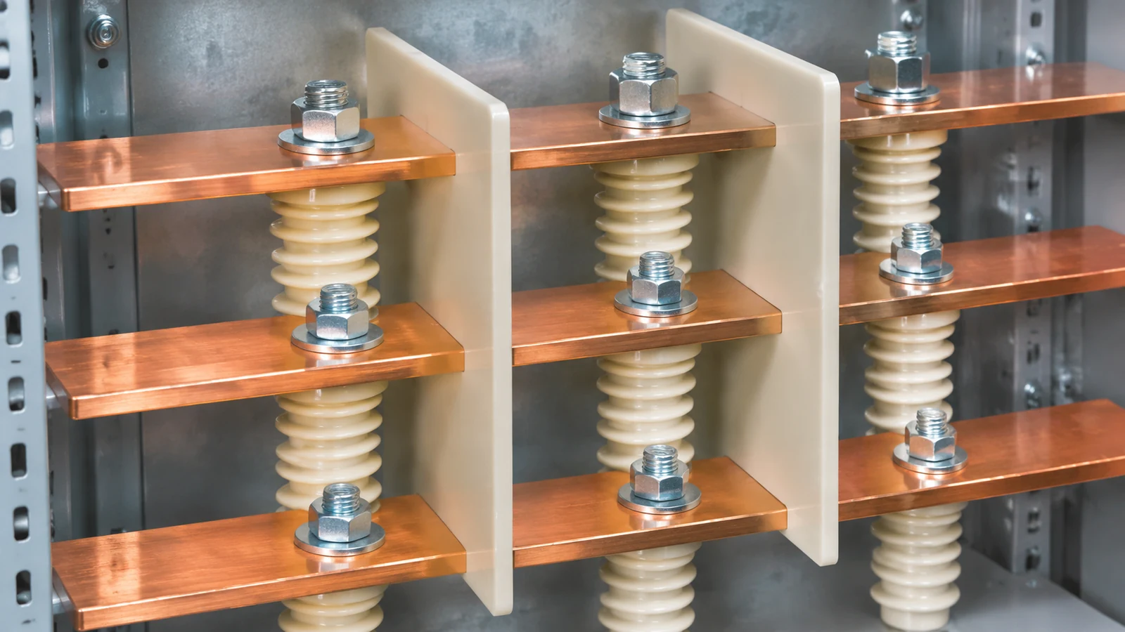
Once the section is chosen, how it is mounted decides whether it holds its rating. The bar has to sit on insulating supports spaced closely enough to resist the mechanical forces of a short circuit, not merely to carry its own weight, and insulating barriers between the phases prevent accidental contact during maintenance while allowing tighter phase spacing. A free bar and a bar on supports are not the same installation, and the rating reflects that. The rail profiles these devices mount to are covered in our DIN rail sizes guide.
Neutral and earth bars are sized against the phase bars
The phase busbars carry the load current. The neutral bar carries the return current, which is a different number in an unbalanced installation. The earth bar normally carries no current at all until there is a fault.
A working rule in panel practice is that the neutral bar is not sized below half the phase bar cross-section, with these exceptions:
Where significant third-harmonic current is present from non-linear loads, the neutral can carry more than the phase conductors, because triplen harmonics add arithmetically in the neutral. In that case the neutral needs to be equal to or larger than the phase conductors rather than half of them.
The protective conductor should be verified against IEC 61439-1 rather than by applying a flat percentage, and it must run the full board length.
Where the same bar serves both the neutral and the earth function, it must still satisfy the earth conductor requirement, which is the more onerous of the two.
Our neutral and earth bar ranges cover the common cases with sections from 1.5 × 15 mm up through 3 × 25 mm, in screw-terminal, bridge-type and DIN-rail-mounted arrangements, so a panel can be built from one consistent family. The D02 brass bridge type grounding bar and the D06 pure copper neutral bar show the two ends of that range, and our neutral bar size chart works through the way-count and spacing calculation.
Five sizing mistakes that show up on real panels
The same five errors account for most of the busbars that fail in service:
The mistake
What actually happens
What to do instead
Using current density as the rating
The bar passes the formula and runs hot in the enclosure
Verify by temperature-rise test, comparison or calculation
Ignoring the ambient inside the cabinet
Internal temperature is far above room temperature
Apply the correction factor for the actual internal ambient
Applying a free-air rating in a closed enclosure
Restricted airflow means the bar never reaches its rated current
Use the enclosed installation condition from the start
Expecting parallel bars to double the rating
The second bar shades the first and adds far less than expected
Space the bars apart and size from the combined verified rating
Sizing for continuous current only
The bar cannot survive the fault it was never sized for
Check the short-circuit duty and take the larger section
Using current density as the rating. Density gives you a starting size. The rating comes from temperature-rise verification against the actual ambient, enclosure and neighbouring bars.
Ignoring the ambient inside the cabinet. The temperature inside a closed panel with other heat-producing devices is not the room temperature. A bar chosen from a 35 °C table and installed in a 50 °C enclosure loses close to 30 percent of its rating before anything else goes wrong.
Applying a free-air rating inside a closed enclosure. Enclosures restrict airflow. Sandwich busduct construction in particular offers essentially no internal free-air convection, so free-air figures cannot represent the assembly’s behaviour.
Expecting parallel bars to double the rating. The second bar adds about 64 percent, not 100 percent, and loses more if the bars are not spaced apart.
Sizing for continuous current only. The short-circuit duty can demand a larger section than the continuous current does. Check both and take the larger.
Frequently asked questions
What is the current density for copper busbars, and which standard governs the ratings?
Between 1.0 and 1.6 A/mm² is typical practice for preliminary sizing of copper in low-voltage switchgear, with about 1.2 A/mm² a common working value and higher densities used inside ventilated enclosures. IEC 61439-1 does not mandate a fixed density; it requires the finished assembly to be verified by temperature-rise test, comparison or calculation.
On the standards themselves: IEC 61439-1 governs low-voltage assemblies up to 1000 V AC or 1500 V DC and sets the temperature-rise limits and the verification routes, but it does not publish a table of rectangular bar ampacities. DIN 43671 is the standard that carries those tabulated values, referenced at 35 °C ambient and 65 °C bar temperature. In North America the equivalents are UL 891 and NEMA PB 2.
Can I paint a copper busbar?
Yes, and it usually helps. A matte black non-metallic coating raises the surface emission level from about 0.4 to about 0.9, which is worth roughly 20 percent more current in the DIN 43671 tables, and it protects against oxidation. The coating must be electrically insulating and rated for the fault temperatures involved.
How do I size a neutral bar?
Not below half the phase bar cross-section is the usual working rule, verified against the actual neutral load. Where third-harmonic currents are significant, size the neutral equal to or above the phase conductors instead. Our neutral bar range covers sections from 1.5 × 15 mm to 3 × 25 mm in the common mounting arrangements.
What short-circuit current can a busbar withstand?
Use the adiabatic expression A_min = I_k × √t ÷ k, with k of 122 for copper and 81 for aluminium. Then check the mechanical force on the supports, which at high fault levels is usually the governing constraint rather than heating.
Does busbar size affect its current rating?
Yes, and not only through cross-section. Two bars of identical area but different aspect ratio carry different currents because the wider one presents more cooling surface. This is why a wide thin section outperforms a narrow thick one of the same area, and why busbar thickness beyond roughly 20 to 25 mm buys little.
Conclusion
Busbar sizing is a thermal problem dressed up as an arithmetic one. The cross-section you calculate from current density is the starting point; the rating you can rely on comes from a tabulated ampacity adjusted for surface finish, ambient and mounting, verified against IEC 61439-1 temperature-rise limits, and then checked for short-circuit withstand and voltage drop over the actual run.
Our busbar range covers 32 A to 125 A comb and C45 type bars in one, two, three and four pole versions, plus the matching accessories, and we can supply the section data for a specific panel arrangement on request. If you have a panel schedule and want the busbar line items specified against it, send the schedule and we will work it up.
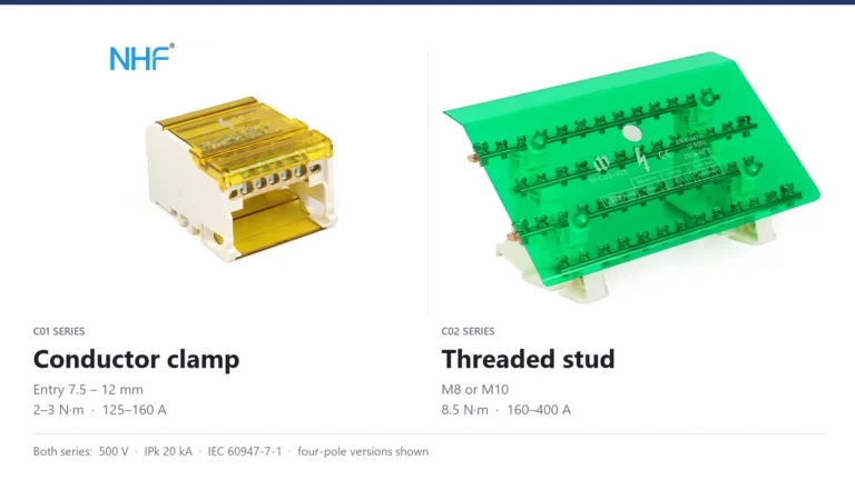
Both ranges are rated 500 V and IPk 20 kA, so the data sheet cannot choose for you. The difference sits at the input terminal: a conductor clamp with a published conductor range, or a stud that holds a cable lug.
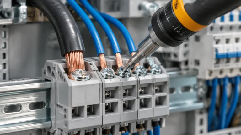
Four rules decide whether a terminal block joint runs cool or overheats: the strip length the block specifies, the separate input and output torque values, one rated conductor per clamp, and the conductor range for the ferruled size.
How to test earth continuity on a grounding bar: the dead test method, instrument and test current selection, acceptance values in ohms, and the parallel-path mistake that invalidates results.