Comb Busbar Current Rating: How Many Amps Can a Pin Busbar Really Carry?
Published: Author: Rachel
This guide covers how a comb busbar current rating is derived, how to read the specification table, and why the published figure differs from a generic copper calculation.
Quick answer: a comb busbar’s current rating is set by its copper cross-section, not by the breaker it feeds. For the pin-type comb busbars used in MCB distribution boards, the relationship runs from 1.0 mm thickness at 32 A up to 2.0 mm at 125 A. If you need more than 125 A through a single bar, you change the bar — you do not change the rating.
Buyers often arrive at the same confusion. They have a 63 A main incoming breaker, they want to feed eight 16 A circuits, and they want to know which busbar “matches” it. The word matches is the problem. A busbar does not match a breaker. It carries whatever current the panel actually draws, and its job is to do that without getting hot enough to damage the plastic housing it is bolted to.
This guide works through what actually determines a comb busbar current rating, how to read the specification tables manufacturers publish, and how to cross-check a rating against the real products in our range. It also covers the four mistakes that show up repeatedly in panel building, including the one that causes most overheated busbars.
What determines a comb busbar current rating
The four factors set the rating. Three of them come from the bar itself; one comes from where you put it. Here is the short version before the detail:
Cross-sectional area — the flat copper body carries the current, and the teeth take up space that reduces the effective section
Copper thickness — increases the section and improves how heat leaves the bar
Tooth pitch — a mechanical constraint set by the breaker family, not an electrical one
Installation conditions — mounting position, enclosure type and ambient temperature
Cross-sectional area
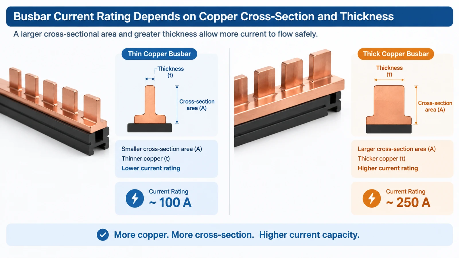
This is the single biggest factor, and it is simply width multiplied by thickness. A comb busbar is not a solid rectangle — it is a flat copper strip with teeth punched upward at regular pitch. Only the flat body carries current from end to end. The teeth exist to plug into the breaker terminals.
Because the teeth take up space, the effective cross-section is less than the overall footprint suggests, which is why manufacturers rate the bar by the body cross-section and publish it separately from the outer dimensions.
Copper thickness
Thickness matters twice over. It increases the cross-sectional area directly, and it improves how heat leaves the bar. A wider, flatter bar sheds heat better than a narrow, thick one of the same cross-section, because surface area grows faster than volume.
This is why you will see ranges like 1.0 mm, 1.2 mm, 1.4 mm, 1.7 mm, 1.8 mm and 2.0 mm offered for the same busbar family. They are not arbitrary steps. Each step corresponds to a current rating where the copper section is resized to suit.
Tooth pitch and breaker compatibility
The tooth pitch — the distance between adjacent teeth — has to match the pitch of the breaker terminals it plugs into. This is a mechanical constraint, not an electrical one, but it removes your freedom of choice. A 63 A single-module MCB and a 32 A single-module MCB may look similar from the front and have completely different terminal pitch, and no busbar will serve both.
This is where the MCB busbar compatibility guide comes in — it covers the pin-versus-fork difference, the breaker series and pole pitch checks, and the step-by-step matching process, while pin type vs fork type busbars explains the mechanical difference between the two families.
Installation conditions
The rating published on a datasheet assumes a specific mounting condition and ambient temperature. A bar mounted flat against a steel backplate, inside a sealed enclosure in a hot plant room, will run hotter than the same bar mounted free in a ventilated switchboard.
This is why two identical bars can carry different current in two different cabinets, and why you should never size a bar purely from the rating table without checking the installation conditions.
Reading a busbar specification table
Manufacturers publish busbar ratings in a consistent format. The table below is taken from our own pin type range and shows the format you will find across the industry — model number, carrying current, thickness, cross-sectional area, then the physical dimensions.
Model
Carrying current
Thickness
Sectional area
Poles
Length A (mm)
Tooth pitch B (mm)
Tooth width C (mm)
Tooth height D (mm)
H-101/1P-54
32 A
1.0 mm
5 mm²
54
1000
18
4
12
H-101/1P-54
40 A
1.2 mm
6 mm²
54
1000
18
4
12
H-101/1P-54
63 A
1.4 mm
10 mm²
54
1000
18
4
12
H-101/1P-54
80 A
1.7 mm
15 mm²
54
1000
18
4
12
H-101/1P-54
100 A
1.8 mm
16 mm²
54
1000
18
4
12
H-101/1P-54
125 A
2.0 mm
18 mm²
54
1000
18
4
12
Three things in that table are worth pausing on.
First, the rating follows the copper, not the breaker. The same bar body serves 32 A through to 125 A; what changes is the thickness and therefore the copper section. The pole count and length stay constant because they are mechanical dimensions.
Second, thickness is not linear with current. Going from 32 A to 63 A nearly doubles the copper section (5 mm² to 10 mm²), but going from 100 A to 125 A adds only 2 mm². The step between ratings gets tighter as you climb, because the busbar body is already large and the remaining headroom is thin.
Third, note the jump between 40 A and 63 A — 6 mm² to 10 mm². That gap is where a lot of incorrect sizing happens, because 63 A is the most common MCB rating in the world and many people assume it sits halfway between 40 A and 80 A. It does not.
End Feed Versus Centre Feed: The Factor Nobody Uses
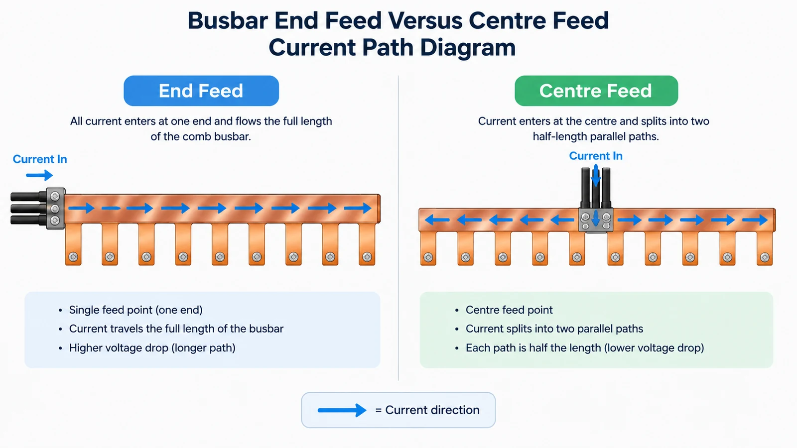
This is the single largest lever on a comb busbar’s real current capacity, and it is printed in the datasheets almost as a footnote.
With an end feed, all current enters at one extremity and flows the full length of the bar to reach the farthest breaker. The whole bar resistance R carries the whole current I, so the heating is I²R.
With a centre feed, the bar behaves as two halves in parallel. Each half has half the resistance, R/2, and carries half the current, I/2. The heating in each half is (I/2)² x (R/2) = I²R/8, and across both halves the total is I²R/4. One quarter of the heat for the same current — which means, since heating scales with the square of current, the same bar can carry twice the current for the same temperature rise.
Feed arrangement
Effective path
Total I²R heating
Typical published rating, 1 m / 25 mm² bar
End feed (side feed)
Full length, single path
I²R
100 A
Centre feed
Two half-length paths in parallel
I²R / 4
200 A
Published figures confirm the arithmetic across independent manufacturers: one European range lists 100 A IEC with 200 A for centre feed on the same 25 mm², 1 m article; a UL-listed comb busbar range is 100 A end-fed and 200 A centre-fed; one Asian manufacturer’s catalogue gives 100 A end feed against 110 A centre feed on a 25 mm² part — the same direction, a smaller margin, which is what you get when the limiting factor shifts from the copper to the feeder terminal itself.
The practical consequence is straightforward. If a board’s incoming current exceeds the end-feed rating, you do not necessarily need a heavier bar. You may only need to move the feed to the middle, using a centre-feed terminal module. That is a cheaper fix than upsizing copper, and it is usually a shorter lead time too.
The caveat: the feeder terminal becomes the limit. A centre feed rated 200 A still has to get 200 A into the bar through one connection, and that connection — its clamping range, its own cross-section and its torque — is what sets the ceiling in the manufacturer’s more conservative listings. Specify the feeder terminal together with the bar, not separately.
How to calculate the current rating yourself
You do not need to guess. The calculation is a single division, and the input you need is already on the datasheet.
Current rating equals cross-sectional area multiplied by allowable current density:
Current (A) = Cross-sectional area (mm²) × Current density (A/mm²)
The variable is current density — how much current each square millimetre of copper is allowed to carry before the bar runs too hot. Published figures for copper in an enclosed panel typically fall between 1.2 and 1.6 A/mm², and around 1.5 A/mm² is a common working figure for ventilated switchgear.
Run that against our own table and the numbers line up:
Thickness
Cross-section
At 1.2 A/mm² (conservative, enclosed panel)
At 1.5 A/mm² (typical switchgear)
Published rating
1.0 mm
5 mm²
6 A
7.5 A
32 A
1.2 mm
6 mm²
7 A
9 A
40 A
1.4 mm
10 mm²
12 A
15 A
63 A
1.7 mm
15.5 mm²
19 A
23 A
80 A
1.8 mm
16.5 mm²
20 A
25 A
100 A
2.0 mm
18 mm²
22 A
27 A
125 A
If you work this backwards from the published ratings, the implied current density lands between 6.4 and 5.8 A/mm² — far above the free-air figures used for bare copper busbar in switchgear.
That is not an error in the datasheet, and it is not a reason to distrust it. It reflects the difference between a bare bar and a comb busbar. A comb busbar is short, wide and buried inside a panel full of plastic components and steel backplates. Its published rating is not a thermal limit on the copper alone; it is a rating for the complete assembly — copper, tooth contact, plastic housing and mounting position — and the contact surfaces at the teeth carry heat away as well as current.
The practical consequence is straightforward: use the published rating, and do not recalculate it from a generic busbar formula. Generic formulas are built for bare bars in open air and will give you a conservative number that is not comparable to the rating on a comb busbar datasheet.
Choosing the right rating for your panel
Now work from the load instead of from the bar. The sequence is short.
Step 1: Calculate the actual load current
Add up the design current of every circuit the bar will feed, and apply your diversity factor if the circuits are not all at full load at once. For a small residential or light commercial board this is usually the sum of the protective device ratings, but for a panel with motor circuits it is worth more than a straight sum.
Step 2: Apply the safety margin
Do not size the bar to exactly the calculated load. Continuous loads — lighting circuits, heaters, anything running for hours — are conventionally sized with headroom. A common rule is to select the next rating up, which for our range means moving from 100 A to 125 A.
Step 3: Check the upstream breaker rating
The busbar rating should be at or above the protective device feeding it. A 63 A incoming breaker feeding a 63 A rated busbar is coherent. A 63 A breaker on a 40 A busbar is not, and the busbar becomes the weak point in the panel.
Step 4: Confirm pitch and pole count
Only now do you look at mechanical dimensions. The pole count must match the number of breakers you intend to feed, and the tooth pitch must match the breaker family. This is where the busbar range comes in — pin type, fork type and C45 type each cover different breaker families.
Ratings by busbar type and pole count
The rating ladder itself is largely independent of busbar type. Pin type, fork type and C45 type bars are all available across a comparable current range, because the current is limited by the copper section and the poles are limited by the pitch.
Where types diverge is the upper end of the range and in the number of poles available. The standard 54-pole pattern with 18 mm tooth pitch covers most MCB applications. Wider 27 mm and 36 mm pitch patterns exist for specific breaker families, and those options are typically restricted to the higher current ratings — which is why the NC series products in our range run from 100 A upward.
Four sizing mistakes that cause overheated busbars
Sizing by breaker rating instead of load
The most common error. A panel full of 16 A circuits does not draw 16 A per breaker; it draws what the connected loads draw. Conversely, a panel with two 32 A motor circuits genuinely needs more than 64 A of busbar, because motors draw high inrush at start.
Ignoring continuous versus intermittent duty
A bar rated 100 A is fine for a load that peaks at 100 A for a few minutes and a serious problem if it runs at 100 A for eight hours. Continuous loads push the bar to a steady-state temperature, and steady state is where the plastic housing starts to age. If the majority of your circuits are continuous, size up one rating step.
Mixing busbar types in one panel
Pin type and fork type bars are not interchangeable, even when the current rating matches. They mate with different terminal designs. If you find yourself forcing a bar into a breaker that does not take it, the mechanical fit is wrong and the contact resistance will be high — which shows up later as heat at exactly one point on the bar.
If you are unsure which type your board uses, our guide to busbar types explains how to identify them, and comb busbar vs jumper wire covers when a busbar is worth the cost over a simpler alternative.
Leaving the incoming connection loose
The rating on the datasheet assumes the bar is properly terminated at both ends. A loose or under-torqued incoming lug adds resistance in series with the bar, and that resistance turns into heat at the connection rather than being spread along the copper. In practice this single fault causes more burned busbars than undersized copper does.
Our overheating guide covers the measurement steps in order, and the compatibility guide linked above explains how to avoid mismatched terminations in the first place.
Busbar accessories and the incoming connection
The busbar is only one part of the circuit. The incoming lug, the barrier and the shroud that carries current from the main switch into the bar are where a lot of panel heat actually originates.
For the standard 25 mm² and 50 mm² sections, TB25 busbar accessories cover the incoming dimensions — the table lists the same section sizes with their D, E and length dimensions so you can match the accessory to the bar and the switch rather than guessing.
Across our standard pin type range, ratings run from 32 A to 125 A. The exact rating for any given bar depends on its thickness and cross-section: 1.0 mm at 5 mm² is rated 32 A, 1.4 mm at 10 mm² is rated 63 A, and 2.0 mm at 18 mm² is rated 125 A.
Can I use a 63 A busbar with a 63 A breaker?
Yes, and that combination is standard practice. The busbar rating should be at or above the incoming protective device rating, never below it. What you cannot do is fit a 40 A rated bar behind a 63 A breaker and expect it to survive the fault current that device is there to interrupt.
Does the number of poles affect the current rating?
Not directly. The pole count determines how many breakers the bar can feed and affects its length, but the current rating is set by the copper cross-section. A 4-pole and a 1-pole bar of the same thickness and section carry the same current.
How many circuits can I feed from one comb busbar?
As many as the pole count allows, within the current rating. A 54-pole bar covers 54 single-module breakers, and a 13P bar covers 13. The constraint is always the current, not the count — 54 circuits at 16 A each is 864 A, far beyond anything a single comb bar carries, so in practice you split the load across several bars or step up to a distribution block.
Why does my busbar run hot when the breakers are not tripped?
The breaker rating is not the load. If the bar is warm, check the actual measured current first, then the torque on the incoming connection, then the contact fit. A high-resistance connection at a single point produces a hot spot long before the copper itself would. The overheating guide walks through the diagnosis in order.
What is the difference between a 32 A and a 63 A busbar?
Both fit the same breakers, because the pole count and tooth pitch are mechanical properties that do not change with current. What changes is the copper: 1.0 mm and 5 mm² for 32 A versus 1.4 mm and 10 mm² for 63 A. The heavier section carries more current and sheds heat faster, which is why the step between 40 A and 63 A is proportionally the largest in the range.
Summary
A comb busbar current rating is a property of the copper section, and the table on the datasheet is the authority. Cross-section and thickness set the rating; pitch and pole count set what the bar can connect to; installation conditions determine how much of the published rating you actually get.
When you are choosing a bar for a panel, work from the load, add margin for continuous duty, check that the rating sits at or above the incoming breaker, and confirm mechanical compatibility before ordering. Our full busbar range covers pin type, fork type and C45 type across 32 A to 125 A, and if you need help matching a bar to a specific panel layout, send us the breaker list and we will work out the configuration.
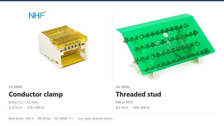
Both ranges are rated 500 V and IPk 20 kA, so the data sheet cannot choose for you. The difference sits at the input terminal: a conductor clamp with a published conductor range, or a stud that holds a cable lug.
Four rules decide whether a terminal block joint runs cool or overheats: the strip length the block specifies, the separate input and output torque values, one rated conductor per clamp, and the conductor range for the ferruled size.
How to test earth continuity on a grounding bar: the dead test method, instrument and test current selection, acceptance values in ohms, and the parallel-path mistake that invalidates results.