An MCB busbar (also called a comb busbar) distributes one supply to a whole row of miniature circuit breakers, saving dozens of parallel wires. But it only works when it matches the breakers. A busbar is compatible with an MCB when four things line up: the terminal type (pin or fork), the breaker series and pole pitch, the pole and phase configuration, and the electrical ratings. A mismatch rarely fails instantly; it creates a weak contact that heats up slowly and damages the board under load. This guide walks through each compatibility check with the busbar ranges designed for standard modular breakers.

Quick Answer: What Makes a Busbar Compatible with an MCB?

Four checks decide compatibility, and they must all pass:

  1. Terminal type: pin-type busbars insert pins into the MCB terminal opening; fork-type busbars slide fork teeth into a screw clamp. They are not interchangeable.
  2. Breaker series and pitch: the busbar must be designed for the same breaker family, with teeth spaced at the exact pole pitch (typically 17.5 mm or 18 mm per pole for modular MCBs).
  3. Poles and phase sequence: a 1P, 2P, 3P, or 4P busbar must match the breaker arrangement, with the correct L1/L2/L3/N sequence.
  4. Ratings: the busbar current rating must cover the main switch feed, the voltage must match the system, and the short-circuit withstand must fit the panel’s fault level.

If the row also contains RCCBs or RCBOs, verify their terminal depth, neutral position, and compatibility separately, because their geometry often differs from plain MCBs.

Step 1: Match the Terminal Type — Pin or Fork

The terminal geometry is the first and most important check. A pin busbar and a fork busbar look similar from a distance, but they contact the breaker in different ways:

  • Pin-type busbar: round or rectangular pins insert straight into MCB terminals designed to accept them. The pins are usually held by the terminal’s screw or cage clamp, so tighten them to the breaker’s torque specification.
  • Fork-type busbar: fork-shaped teeth slide into a screw-clamp terminal area and are captured under the screw. The fork must be fully seated, not floating under the screw head.

Using the wrong geometry creates partial contact, which adds resistance, generates heat, and can cause arcing. Always confirm the busbar type against the MCB datasheet or a physical sample before installing. For a deeper comparison, see our pin-type vs fork-type busbar guide.
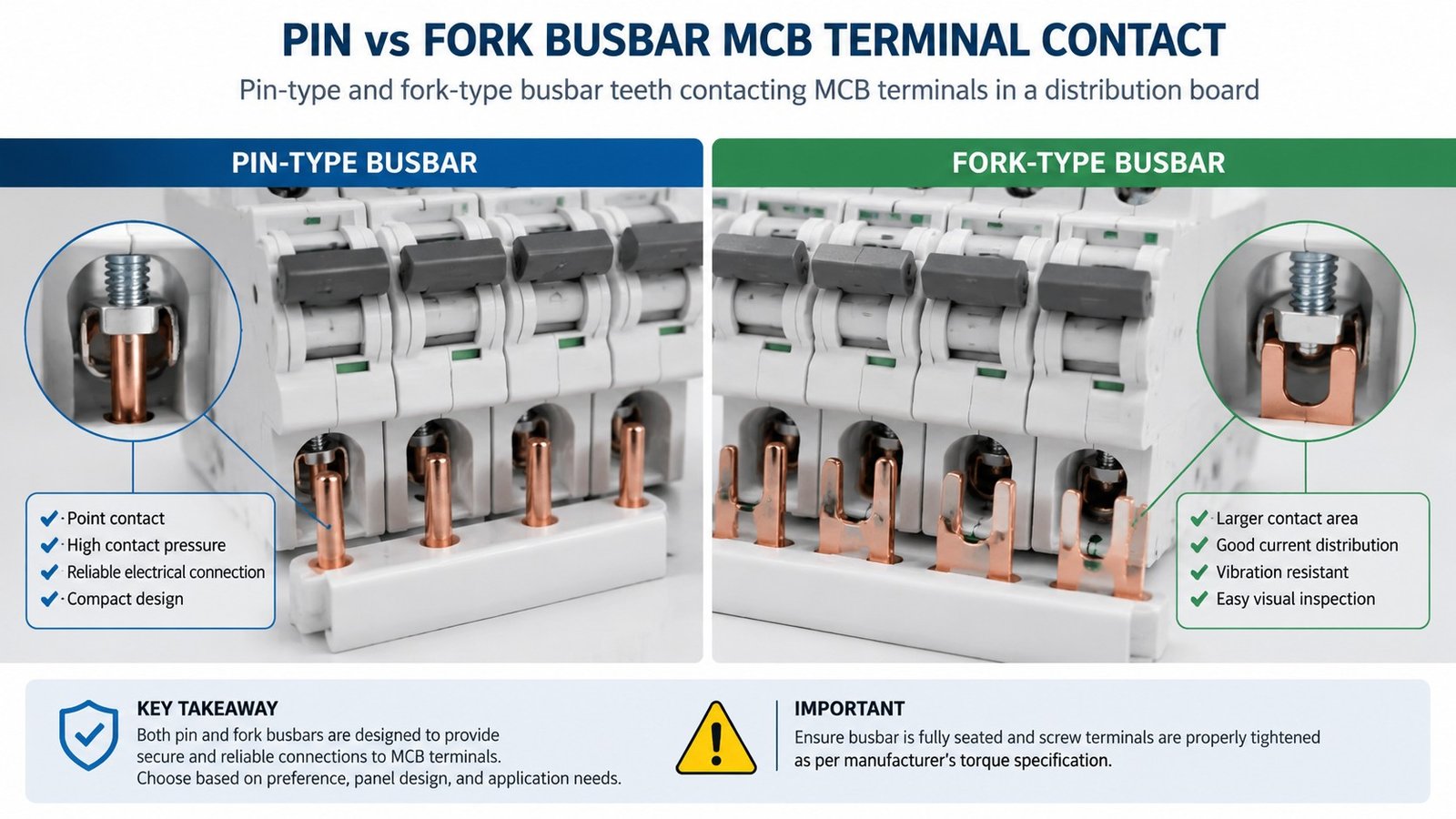
Pin-type and fork-type busbar teeth contacting MCB terminals

Step 2: Match the Breaker Series and Pole Pitch

Even two breakers of the same width can have terminals at different depths or positions. A busbar is engineered for a specific breaker family, so match the series first. Common modular families include C45-type, DPN-type, and universal pin/fork styles:

  • C45-type busbars are designed for C45-series MCBs in single, two, three, and four-phase configurations.
  • DPN and DPNLE busbars serve DPN-style single-pole-plus-neutral devices, where the neutral position matters.
  • Universal pin and fork busbars in 1P, 2P, 3P, and 4P versions cover standard modular rows with matching pitch.

Check the pitch: the center-to-center distance between busbar teeth must equal the pole spacing of the breakers, usually 17.5 mm or 18 mm per module. If the pitch is wrong, the teeth cannot align with the terminals at all.

Step 3: Match the Pole Configuration and Phase Sequence

The busbar must match the electrical arrangement of the row:

  • 1-phase busbar: feeds a row of 1P MCBs from a single-phase supply.
  • 2-phase busbar: for two-pole devices or split-phase arrangements.
  • 3-phase busbar: repeats the L1/L2/L3 sequence across a row of 3P or single-pole outgoing breakers; the phase order must match the device layout.
  • 4-phase busbar: adds the neutral path for three-phase-plus-neutral panels; confirm the neutral tooth position against RCCB/RCBO devices.

A 3-phase busbar is not just a longer 1-phase bar. Its teeth are arranged in a repeated phase sequence, and installing it on the wrong device layout can feed the wrong pole or leave live teeth exposed.
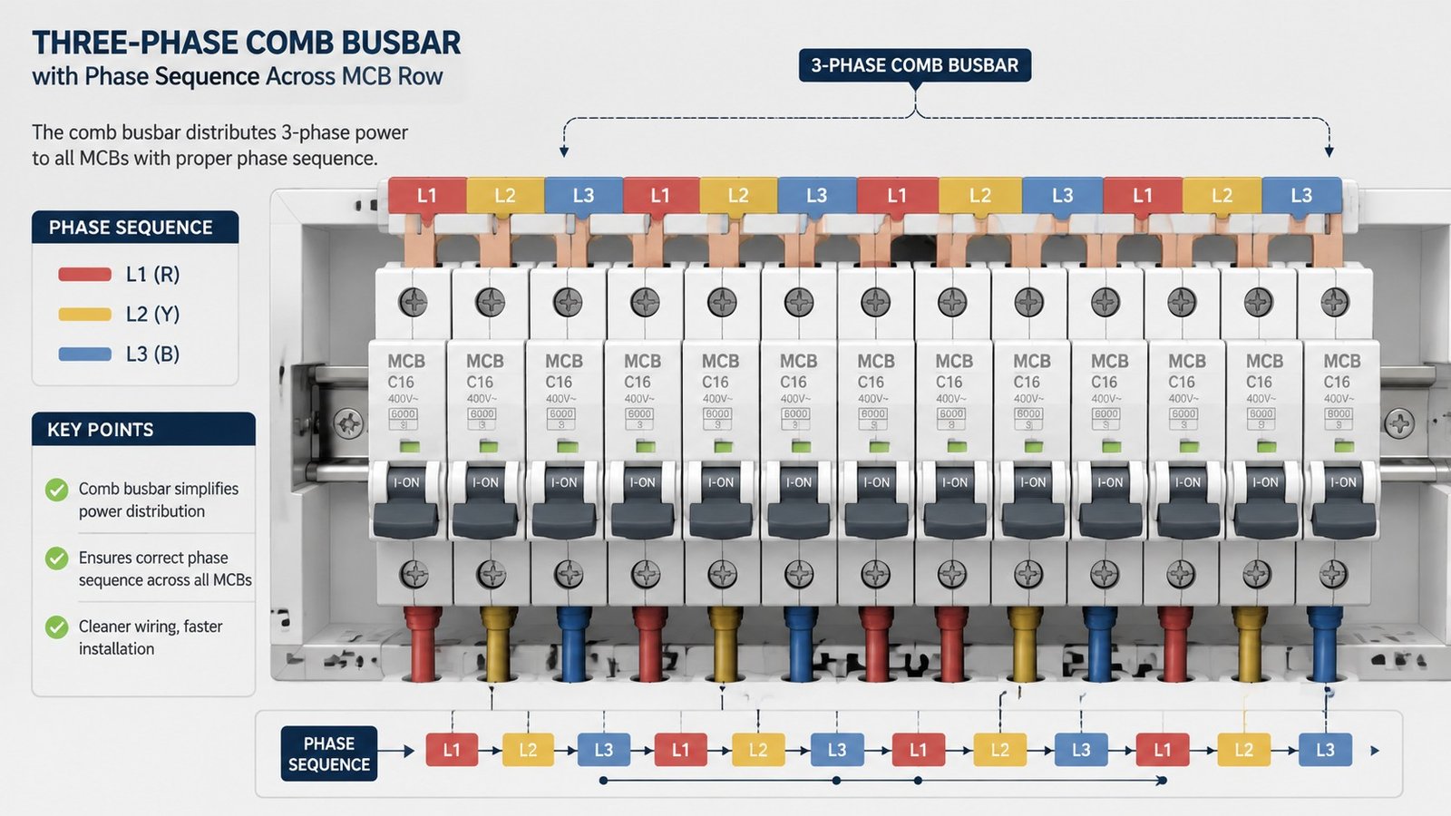
Three-phase comb busbar with phase sequence across a row of MCBs

Step 4: Check the Current, Voltage, and Short-Circuit Ratings

Once the physical match is confirmed, verify the electrical ratings:

  • Current rating: size the busbar against the incoming main switch rating, not the arithmetic sum of every MCB. Diversity means the final-circuit MCBs do not all draw full current at once, so the busbar tracks the feed, not the total of the ways.
  • Voltage rating: the busbar and its insulation must match the system voltage.
  • Short-circuit withstand: the busbar must withstand the prospective short-circuit current at its location, typically 25 kA or higher for demanding installations, coordinated with the upstream protective device.

Most modular MCB busbars are rated between 40 A and 125 A for standard distribution boards, with the exact figure stated per product. For higher loads, confirm the cross-section and rating with the manufacturer before specifying.

How to Install and Finish a Cut Busbar

Cut-to-length busbars need correct finishing to stay safe:

  1. Cut to the exact number of modules you need, and remove teeth for any position that must stay isolated.
  2. Fit end caps on every cut end. Exposed copper is a shock and short-circuit hazard.
  3. Feed the correct side of the breaker row per the device markings, and tighten each terminal to the breaker’s torque specification.
  4. Verify seating: every tooth must be fully inserted and clamped; a tilted or loose breaker means the busbar is applying uneven pressure.
  5. Install insulation covers over unused teeth or positions for touch protection.

Busbar accessories such as end caps, feed connectors, and covers are available for standard ranges, for example the TB25 busbar accessories series.

Common Compatibility Mistakes

  • Using a pin busbar on a fork-only breaker, or vice versa. The geometry looks close but makes poor contact and runs hot.
  • Mixing breaker brands or families in one row. Two 18 mm breakers may still have terminals at different depths, making the busbar sit unevenly.
  • Leaving cut ends exposed. Always cap the ends with insulating end caps.
  • Feeding the wrong side of the breaker. Follow the line/load markings on the device, not a habit.
  • Replacing a busbar with short jumper wires. Jumpers introduce inconsistent tightening, crowding, and overheating in a panel designed for a busbar.
  • Ignoring neutral arrangement on 4P rows. A neutral error causes nuisance tripping or unsafe operation.

FAQ

How do I know if a busbar is compatible with my MCB?

Check four things: the terminal type (pin or fork), the breaker series and pole pitch, the pole and phase configuration, and the current, voltage, and short-circuit ratings. All four must match.

Can I use a pin busbar on a fork-type MCB?

No. Pin and fork busbars use different contact geometries and are not interchangeable unless the MCB manufacturer explicitly allows it.

What pitch do MCB busbars use?

Standard modular MCBs use a pole pitch of about 17.5 mm or 18 mm per module. The busbar teeth must match this center-to-center spacing.

How do I choose the current rating for an MCB busbar?

Size the busbar against the incoming main switch rating rather than the sum of all MCB ratings, because diversity means not all circuits draw full current at once.

Do I need end caps on a cut busbar?

Yes. Every cut end must be finished with an insulating end cap to prevent shock and short circuits.

Can a busbar feed a row with mixed MCBs, RCCBs, and RCBOs?

Only if the busbar is verified against each device’s terminal depth, neutral position, and compatibility, because these devices often have different geometry from plain MCBs.

Conclusion

Matching a busbar to your circuit breakers is a four-step check: terminal type, breaker series and pitch, pole and phase configuration, and electrical ratings. Get all four right and the row distributes power cleanly with fewer wires and fewer failure points; get one wrong and a weak contact will heat up over time. Choose the busbar for your breaker family, cap every cut end, and verify each tooth is seated and torqued. For standard modular rows, browse the busbar range, including C45-type, pin-type, fork-type, and DPN-type busbars, or contact the manufacturer to confirm the match for your breaker lineup.


Previous Post

Power Distribution Block vs Terminal Block: What's the Difference?

Next Post

Why Is My MCB Busbar Overheating? Causes and Fixes

Related Posts

+86-13758896633 Phone manager@nhele.cn E-mail